
Summit Wagon AWD L4-1795cc 1.8L SOHC (1994)
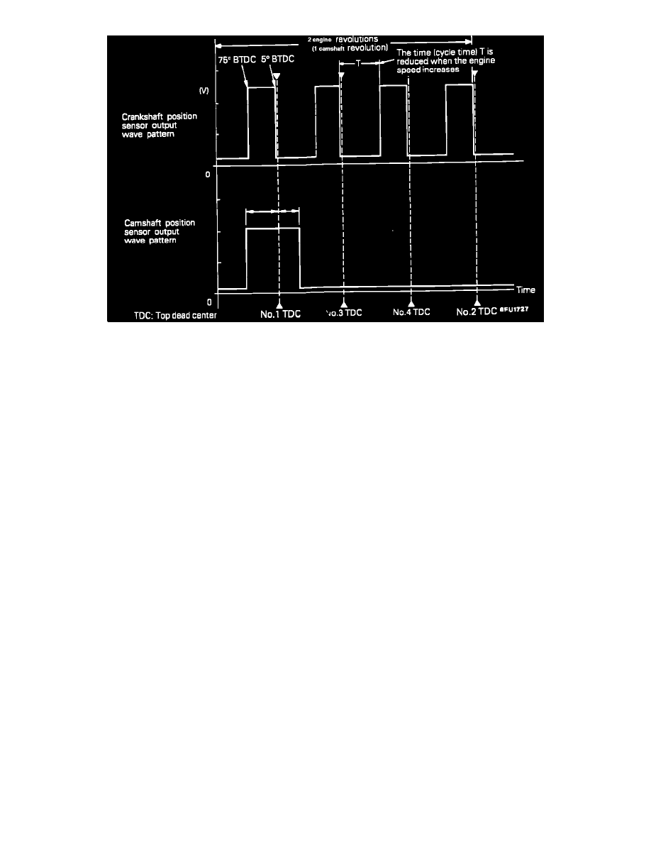
Standard Wave Pattern
OPERATION
-
The crankshaft position sensor detects the crank angle (piston position) of each cylinder. converts it to a pulse signal and inputs it to the engine
control module. The engine control module computes the engine speed and the intake air amount for one stroke and outputs the injector drive
signal and injection command signal based on this signal.
-
Power to the camshaft position sensor is supplied from the MFI relay and the ground is located in the body.
-
A 5V voltage is applied from the engine control module to the camshaft position sensor output terminal and the camshaft position sensor generates
a pulse signal as it switches from OPEN to SHORT (power transistor inside the sensor switches ON/OFF) between the output terminal and the
ground.
CONSTRUCTION
Both sensors are incorporated into one unit consisting of a semiconductor wafer element and a permanent magnet. A rotating shutter called the
trigger wheel acts as a switching device to produce the Hall signal.