
Summit Wagon FWD L4-1795cc 1.8L SOHC (1994)
Wheel Speed Sensor: Testing and Inspection
1. Raise and support vehicle, then release parking brake.
2. Disconnect Electronic Control Unit (ECU) electrical connector, then measure speed sensor output voltage with adapter harness MB991356 or
equivalent connected to harness side connector. Never insert a probe into connector as it may result in poor contact later. Do not connect
connector marked "*" except when recording wave form on a driving test. If necessary, connect connector to ECU.
Fig 69 Wheel Speed Sensor Output Voltage Wave Shape Monitoring Points
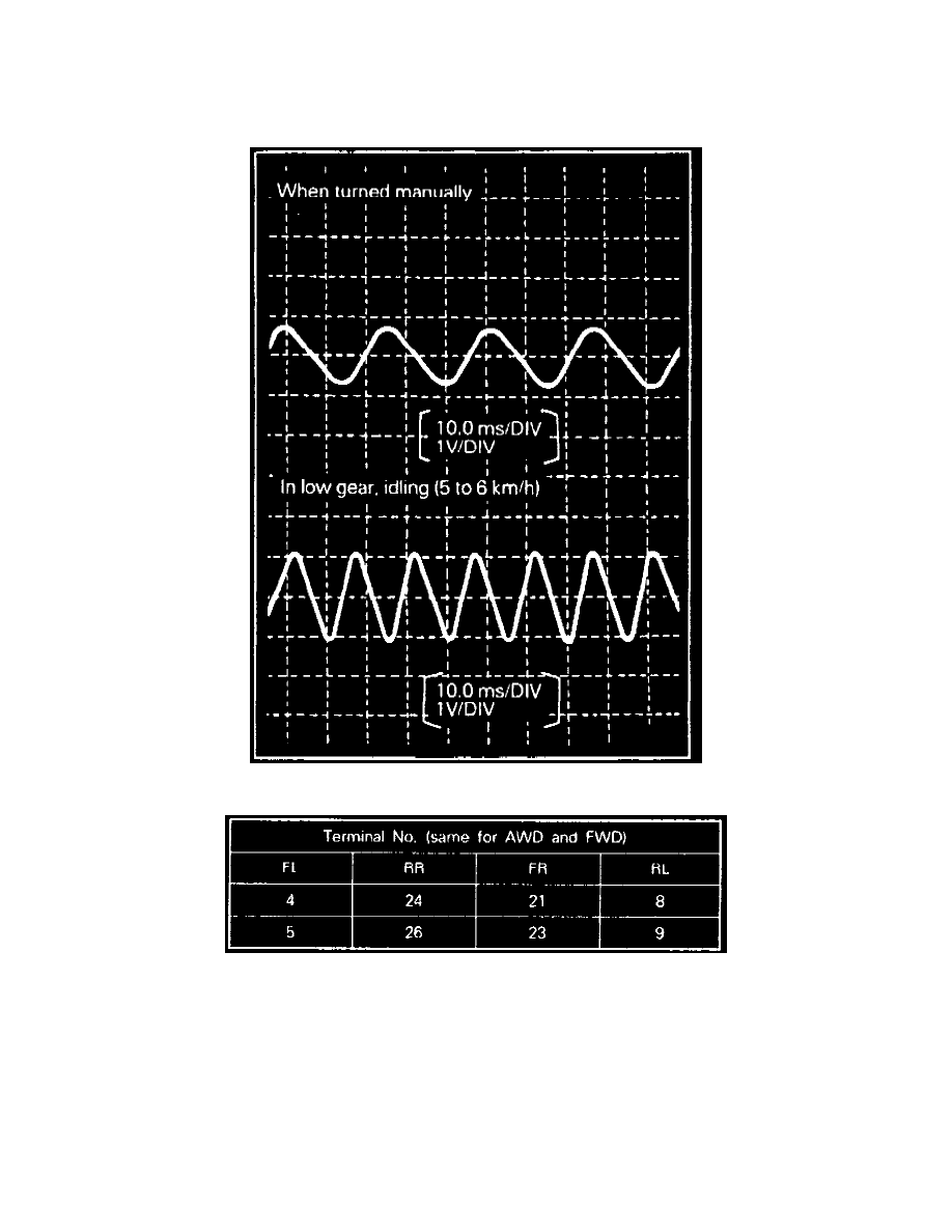
Fig 70 Wheel Speed Sensor Terminal Output Voltages
3. Manually turn wheel to be measured by 1/2-1 turn per second, then measure output voltage with a circuit tester or oscilloscope.
4. Output voltage when measured with a circuit tester should be 70 millivolts (mV) or more.
5. Output voltage when measured with an oscilloscope should be 100 mV or more.
6. Probable causes of low output voltage are: speed sensor pole piece to rotor clearance to great, or faulty speed sensor.
7. To observe output state of wheel speed sensors on front wheels, shift into low gear and drive wheels. On rear wheels turn manually at a constant
speed.
8. Observe output voltage wave form of each wheel speed sensor with an oscilloscope, output voltage is low when wheel speed is low and increases
as wheel speed increases.