
Summit Wagon FWD L4-1795cc 1.8L SOHC (1994)
Throttle Position Sensor
6
Slowly turn the throttle position sensor in the counter clockwise direction until the point at which continuity between terminals G1 and Q2 changes
to non-continuity is found. Tighten the throttle position sensor installation bolt at that position.
7
Connect the connector of the throttle position sensor.
Throttle Position Sensor
8
Connect the scan tool to the data link connector (white).
9
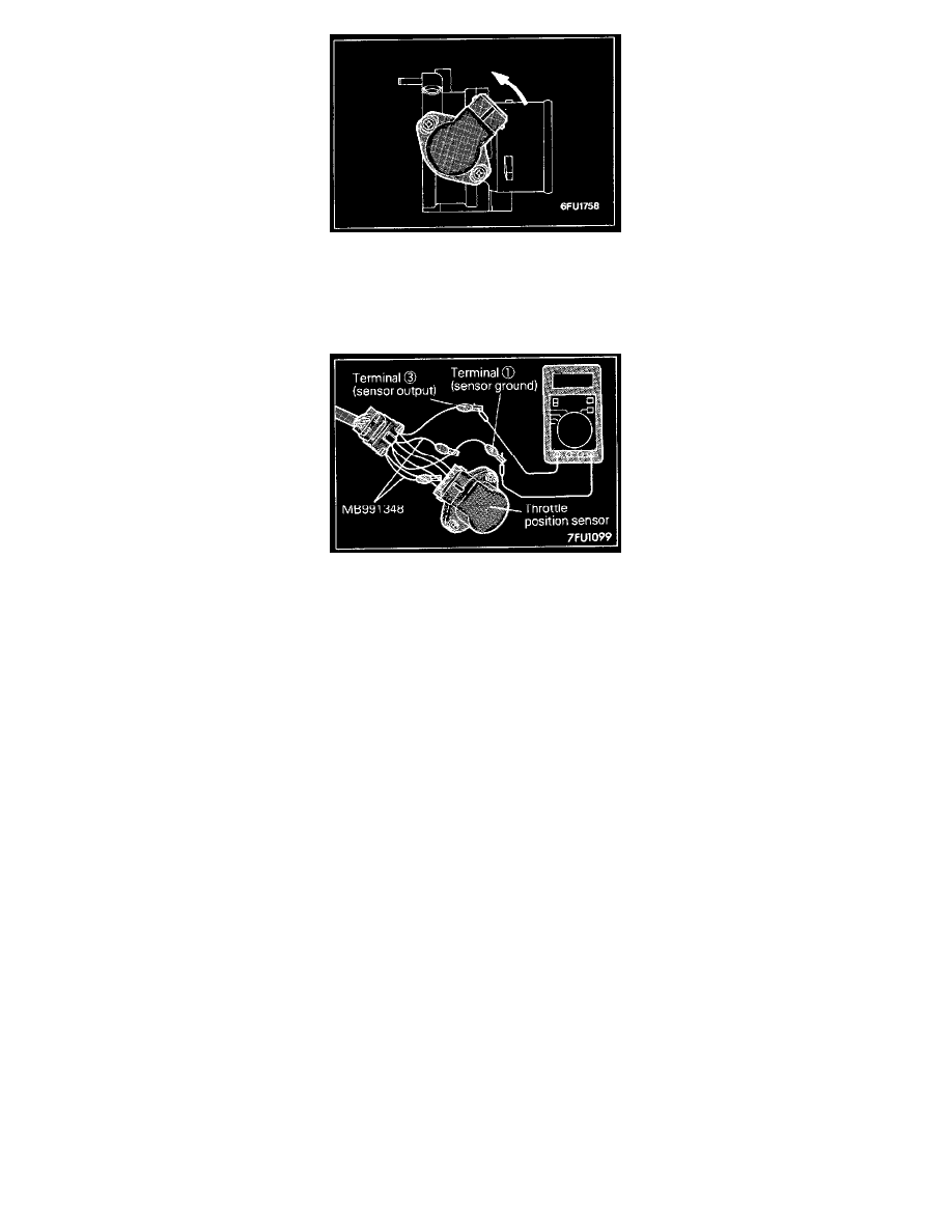
If not using the scan tool proceed as follows:
a. Disconnect the throttle position sensor connectors and connect the special tool Test Harness Set between the disconnected connectors.
b. Connect a digital voltmeter between the throttle position sensor terminal 03 (sensor output) and terminal 01 (sensor ground).
10
Turn the ignition switch ON (but do not start the engine).
11
Check the throttle position sensor output voltage.
-
Standard value: 400-1000 mV
12
If there is a deviation from the standard value check the throttle position sensor and the related harness.
13
Remove the feeler gauge.
14
Switch OFF the ignition switch.