
Summit Wagon FWD L4-2350cc 2.4L SOHC (1995)
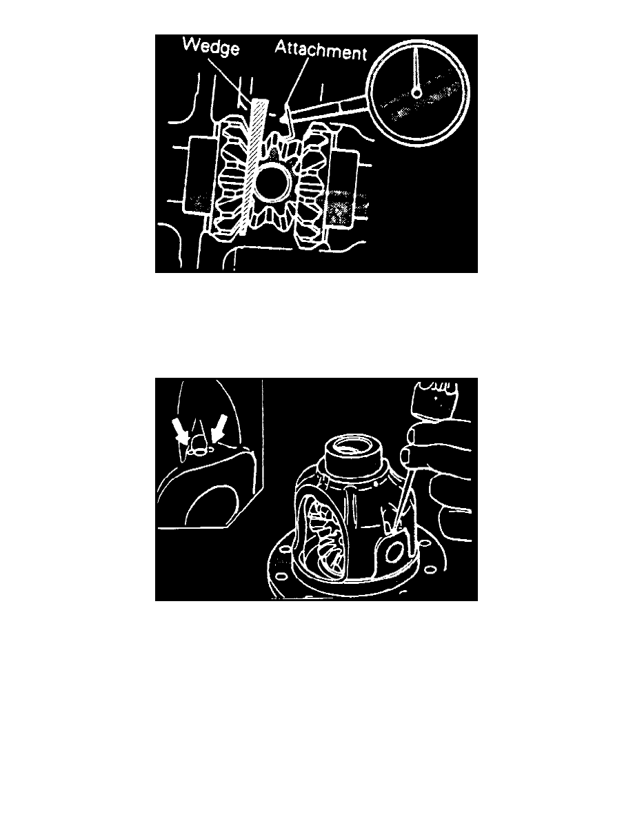
Fig.45 Differential Gear Backlash Check
d. Gear backlash should not exceed 0.008 inch (0.2 mm). If side gear exceeds limit, adjust by installing thicker side gear spacers.
e. After adjustment, ensure differential gear rotates smoothly.
f.
If backlash cannot be adjusted, replace side gear and pinion gear as a set.
g. Align pinion shaft lockpin hole with differential case lockpin hole, and drive in lockpin.
h. Stake lockpin with punch at two points as shown.
Fig.46 Lockpin Installation
6. On all models, clean drive gear attaching bolts, then using a M10 X 1.25 tap, remove adhesive adhering to threaded holes of drive gear. Clean
remaining material out of drive gear using compressed air.
7. Apply multipurpose adhesive Mopar Loctite No. 271 or equivalent to threaded holes of drive gear.
8. Install drive gear onto differential case with mating marks aligned. Torque drive gear attaching bolts in a diagonal sequence to 58-65 ft. lbs.
9. Using bearing installer tool No. MB990728, or equivalent, press side bearing inner races to differential case.
10. Adjust final drive gear backlash as follows:
a. Install side bearing spacers, which are thinner than those removed, to side bearing outer races and then mount differential case assembly into
gear carrier.
NOTE:
Use side bearing spacers with the same thickness for both drive pinion and drive gear sides.
b. Push differential case to one side of the gear carrier and measure clearance between gear carrier and side bearing as shown.