
Talon AWD L4-1997cc 2.0L DOHC Turbo (1991)
Speed Control Servo: Testing and Inspection
Motor Release Direction & Limit Switch Operation
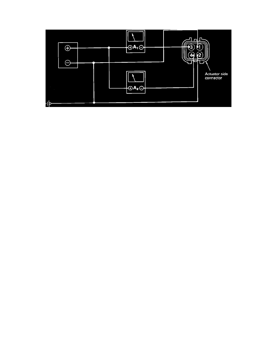
Fig. 97 Motor Release Direction & Limit Switch Operation
1. Connect ammeters to actuator side connector.
2. Turn selector in the Release (fully closed), direction. Current should be cut off, ammeter A1 should read .5-.7 amps and ammeter A2 should read
less than .5 amps when current is On.
3. If selector moves in Release direction, ammeter A1 reads .5-.7 amps, but ammeter A2 reads 1 amp or more, check the following:
a. Improper gear backlash, burning between shaft and metal, or insufficient thrust clearance.
4. If selector does not move, ammeter A1 reads .5-.7 amps, but ammeter A2 reads 1 amp or more, check the following:
a. Burned shaft or motor, or foreign material caught between gears.
5. If selector does not move, ammeter A1 reads 0.3--0.7 amps and ammeter A2 reads 0 amps, check the following:
a. Damaged or disconnected internal lead wire or motor wiring, poor limit switch contact, or open diode.