
Talon FWD L4-1997cc 2.0L DOHC (1990)
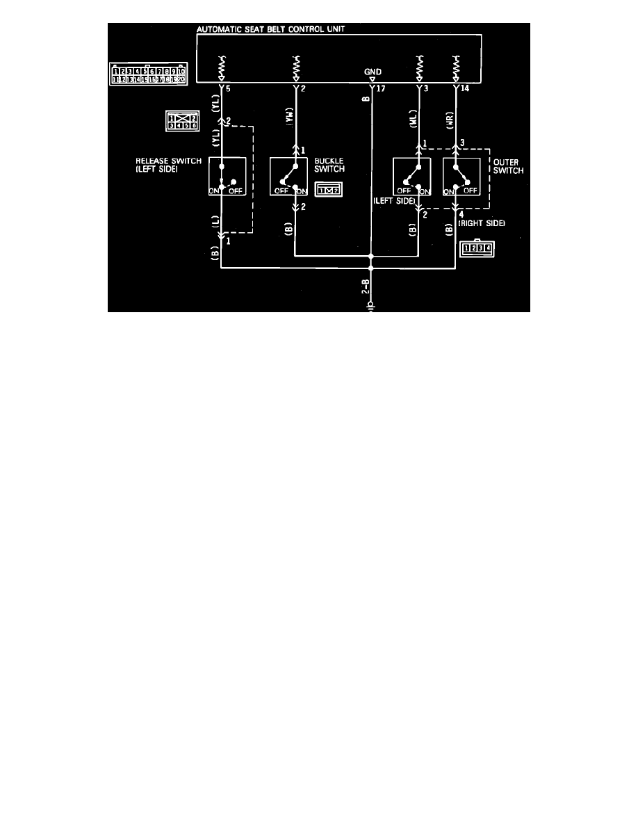
Fig. 145 Release Switch (driver's Side), Buckle Switch & Outer Switch Circuit Diagram
1.
Check release switch (driver side) circuit as follows:
a. Disconnect release switch harness connector.
b. Connect a suitable ohmmeter between release switch connector terminal 1 and ground.
c. Ohmmeter should indicate continuity.
d. If continuity is indicated, circuit is satisfactory. Proceed to step f.
e. If continuity is not indicated, repair harness as necessary.
f.
Connect release switch harness connector, then disconnect control unit harness connector.
g. Connect ohmmeter between control unit connector terminal 5 and ground.
h. Observe ohmmeter while manually moving slide anchor.
i.
Ohmmeter should indicate continuity when slide anchor is not in release (switch On) range.
j.
Ohmmeter indicate infinite ohms when slide anchor is in release (switch Off) range.
k. If resistance indicated is as specified, circuit is satisfactory. Proceed to step 2.
l.
If resistance indicated is not as specified, repair harness or replace motor and track assembly as necessary.
2.
Check buckle switch circuit as follows:
a. Disconnect buckle switch harness connector.
b. Connect a suitable ohmmeter between buckle switch connector terminal 2 and ground.
c. Ohmmeter should indicate continuity.
d. If continuity is indicated, circuit is satisfactory. Proceed to step f.
e. If continuity is not indicated, repair harness as necessary.
f.
Connect buckle switch harness connector, then disconnect control unit harness connector.
g. Connect ohmmeter between control unit connector terminal 2 and ground.
h. Ensure lap belt is not fastened.
i.
Ohmmeter should indicate continuity.
j.
If continuity is indicated, circuit is satisfactory. Proceed to step 3.
k. If continuity is not indicated, repair harness or replace buckle as necessary.
3.
Check outer switch circuit as follows:
a. Disconnect outer switch harness connector.
b. Connect ohmmeter between outer switch connector (harness side) terminal 2 and ground, then terminal 4 and ground.
c. Ohmmeter should indicate continuity.
d. If continuity is indicated, circuit is satisfactory. Proceed to step f.
e. If continuity is not indicated, repair harness as necessary.
f.
Connect ohmmeter between outer switch connector (switch side) terminals 1 and 2 (left side), then between terminals 3 and 4 (right side).
g. Observe ohmmeter while pulling out and retracting shoulder belt.
h. With shoulder belt fully retracted to pulled out approximately half way (outer switch Off), infinite ohms should be indicated.
i.
With shoulder belt pulled half way out to fully pulled out position (outer switch On), continuity should be indicated.
j.
If resistance indicated is as specified, circuit is satisfactory. Proceed to step l.
k. If resistance indicated is not as specified, replace shoulder belt retractor assembly.
l.
Connect shoulder belt to slide anchor (outer switch On). Connect outer switch harness connector, then disconnect control unit harness