
Talon FWD L4-1997cc 2.0L DOHC Turbo VIN F SMFI (1998)
OPERATIONAL CHECK
1. Remove the throttle body.
2. Remove the stepper motor.
3. Connect the special tool (test harness) to the idle air control motor connector.
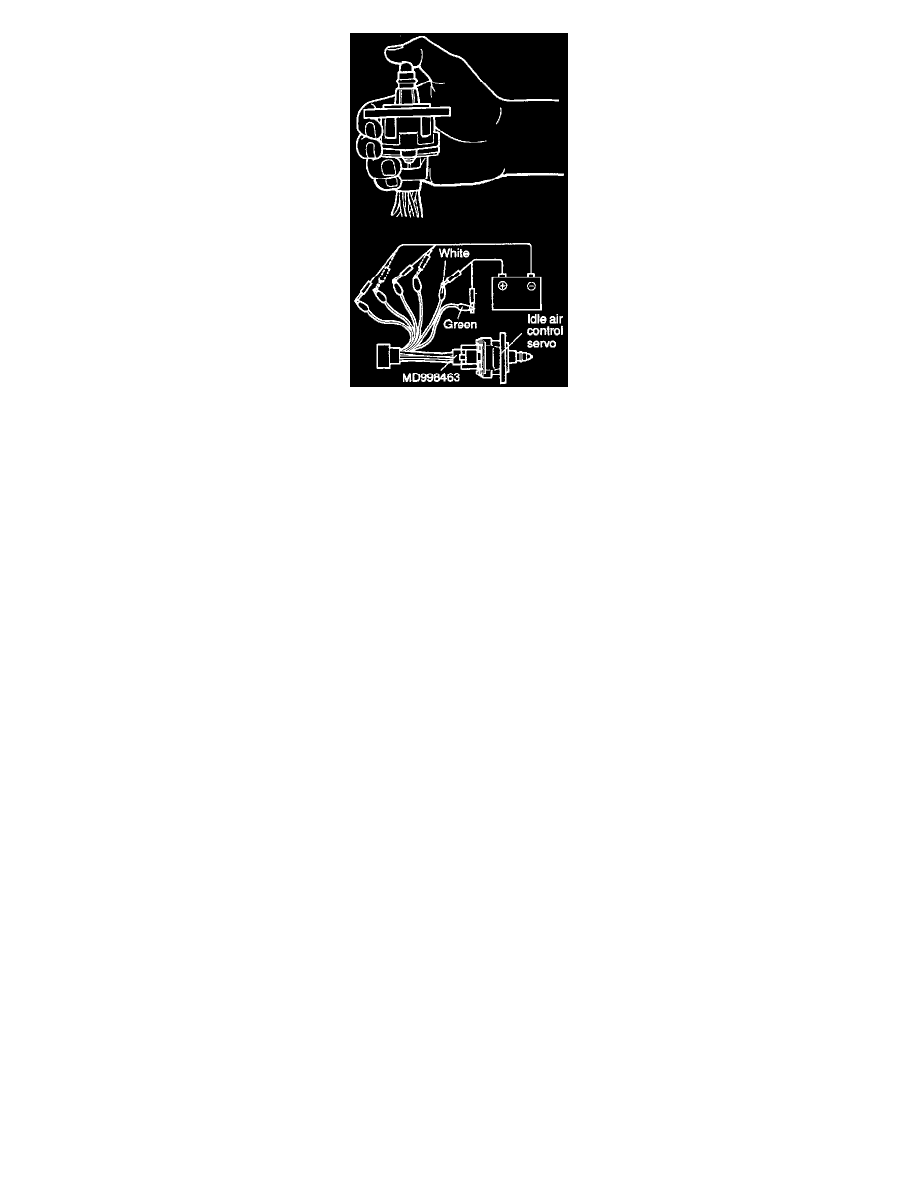
4. Connect the positive (+) terminal of a power supply (approx. 6V) to the white clip and the green clip.
5. With the idle air control motor as shown in the illustration, connect the negative (-) terminal of the power supply to each clip as described in the
following steps, and check whether or not a vibrating feeling (a feeling of very slight vibration of the stepper motor) is generated as a result of the
activation of the stepper motor.
a. Connect the negative (-) terminal of the power supply to the red and black clip.
b. Connect the negative (-) terminal of the power supply to the blue and black clip.
c. Connect the negative (-) terminal of the power supply to the blue and yellow clip.
d. Connect the negative (-) terminal of the power supply to the red and yellow clip.
e. Connect the negative (-) terminal of the power supply to the red and black clip.
f.
Repeat the tests in sequence from (5) to (1).
6. If, as a result of these tests, vibration is detected, the stepper motor can be considered to be normal.