
Talon FWD L4-1997cc 2.0L DOHC Turbo VIN F SMFI (1998)
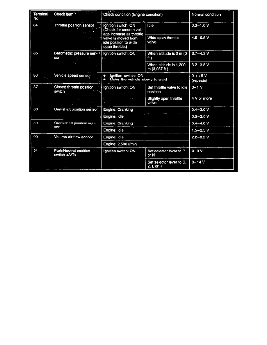
2. Insert the needle-nosed wire probe into each of the ECM connector terminals from the wire side, and measure the voltage while referring to the
chart.
NOTES:
1. Measure voltage with the ECM connectors connected.
2. You may find it convenient to pull out the ECM to make it easier to reach the connector terminals.
3. Checks don't have to be carried out in the order given in the chart.
CAUTION: Short circuiting the positive (+) probe between a connector terminal and ground could damage the vehicle wiring, the sensor, the
ECM, or all three. Use care to prevent this!
3. If voltmeter shows any division from standard value, check the corresponding sensor, actuator and related electrical wiring, then repair or replace.
4. After repair or replacement, recheck with the voltmeter to confirm that the repair has corrected the problem.
Terminal Resistance and Continuity Checks
1. Turn the ignition switch to OFF.
2. Disconnect the ECM connector.