
Talon FWD L4-1997cc 2.0L DOHC VIN Y SMFI (1997)
Electronic Brake Control Module: Testing and Inspection
Resistance Check
ABS-ECU CONNECTOR TERMINAL ARRANGEMENT
ABS-ECU Connector Terminal Arrangement
CAUTION:
1. Use the special tool (MB991356), or equivalent to check the Antilock Brake System (ABS) - Electronic Control Unit (ECU) terminal voltage and
resistance.
2. The ABS-ECU connector terminal arrangement for troubleshooting is different from the terminal arrangement shown on the special tool
connector. So take the readings from the terminal numbers of the special tool when checking.
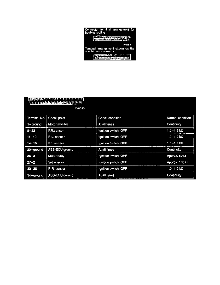
Terminal Resistance & Continuity Check Chart
TERMINAL RESISTANCE AND CONTINUITY CHECK
1. Turn the ignition switch to OFF.
2. Disconnect the ABS-ECU connector.
3. Measure the resistance and check for continuity between the terminals of the ABS-ECU harness-side connector while referring to the check chart.
CAUTION:
-
If resistance or continuity checks are performed on the wrong terminals, damage to the vehicle wiring, sensors, ABS-ECU, and/or ohmmeter
may occur. Use care to prevent this!
NOTE:
-
When measuring resistance and checking continuity, a harness for checking contact pin pressure should be used instead of inserting a test
probe.
-
Checks do not have to be carried out in the order given in this chart.
4. If the ohmmeter shows any deviation from the normal condition, check the corresponding sensor, actuator and related electrical wiring, and then
repair or replace.
5. After repair or replacement, recheck with the ohmmeter to confirm that the repair or replacement has corrected the problem.