
Talon FWD L4-1997cc 2.0L DOHC VIN Y SMFI (1997)
Measuring Terminal Voltage With Voltmeter Probe
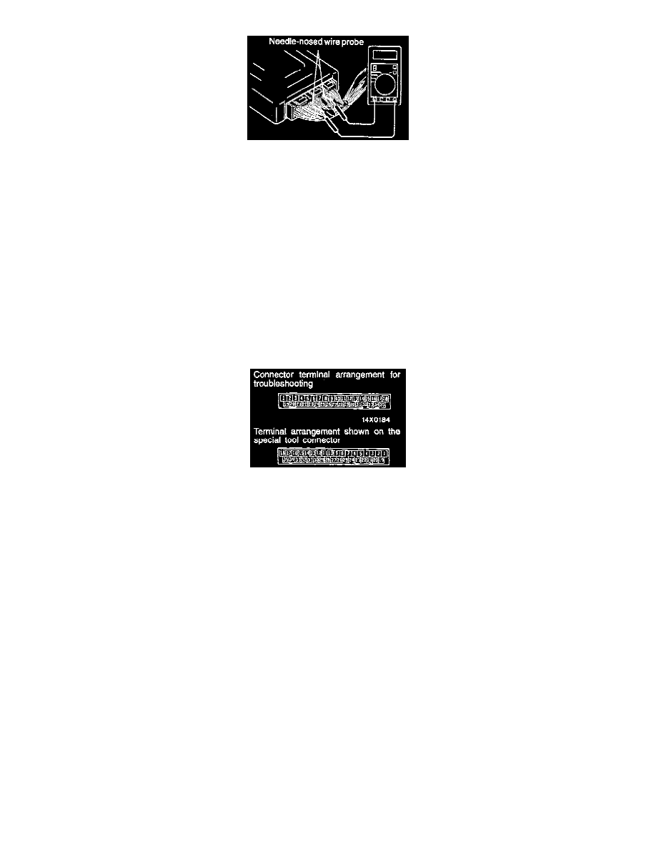
2. Insert the needle-nosed wire probe into each of the Antilock Brake System (ABS) - Electronic Control Unit (ECU) connector terminals from the
wire side, and measure the voltage while referring to the check chart.
NOTE:
a. Measure voltage with the ABS-ECU connectors connected.
b. You may find it convenient to pull out the ABS-ECU to make it easier to reach the connector terminals.
c
.Checks don't have to be carried out in the order given in the chart.
CAUTION: Short-circuiting the positive (+) probe between a connector terminal and ground could damage the vehicle wiring, the sensor,
ABS-ECU, or all three. Use care to prevent this!
3. If voltmeter shows any division from standard value, check the corresponding sensor, actuator and related electrical wiring, then repair or replace.
4. After repair or replacement, recheck with the voltmeter to confirm that the repair has corrected the problem.
ABS-ECU Connector Terminal Arrangement
ABS-ECU Connector Terminal Arrangement
CAUTION:
1. Use the special tool (MB991356), or equivalent to check the ABS-ECU terminal voltage and resistance.
2. The ABS-ECU connector terminal arrangement for troubleshooting is different from the terminal arrangement shown on the special tool
connector. So take the readings from the terminal numbers of the special tool when checking.