
Talon FWD L4-1997cc 2.0L DOHC VIN Y SMFI (1997)
Measuring Resistance Between Terminals (1) & (2) And Body Of Wheel Speed Sensor
INSULATION CHECK
1. Remove all connections from the wheel speed sensor, and then measure the resistance between terminals (1) and (2) and the body of the wheel
speed sensor.
Standard value: 100K or more
2. If the wheel speed sensor insulation resistance is outside the standard value range, replace with a new wheel speed sensor.
Wheel Speed Sensor Output Voltage Check
Measuring Wheel Speed Sensor Output Voltage
OUTPUT VOLTAGE CHECK
1. Lift up the vehicle and release the parking brake.
2. Disconnect the Electronic Control Unit (ECU) harness connector and measure from the harness side connector.
CAUTION: Set the special tool and use the check connector to check. Do not connect the connector (Special Tool) marked with "*" except when
recording the waveform on a driving test. In such a case, connect the connector to the ECU.
3. Rotate the wheel to be measured at approximately 1/2 - 1 rotation per second, and check the output voltage using a circuit tester or an oscilloscope.
Output voltage
When measuring with a voltmeter: 70 mV or more
When measuring with an oscilloscope: 200 mV p-p or more
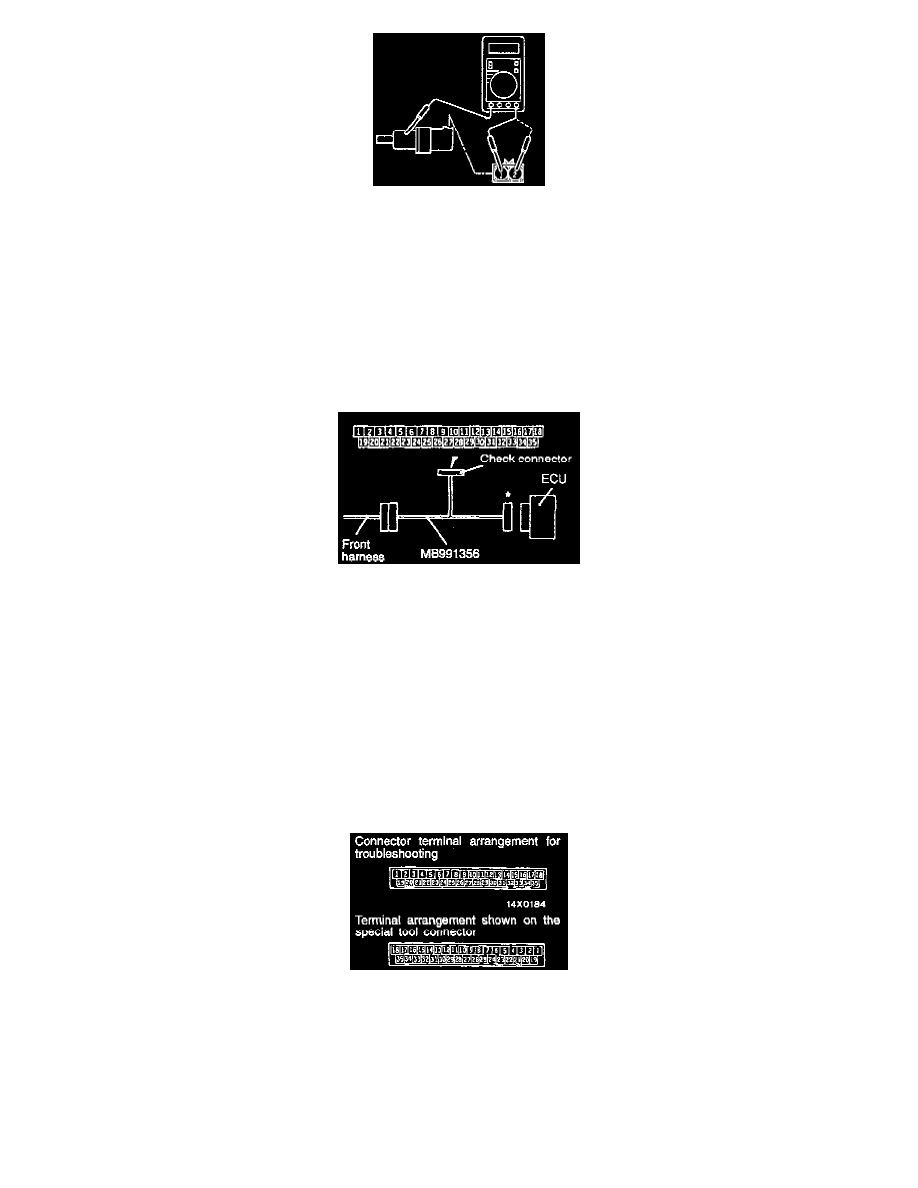
ABS-ECU Connector Terminal Arrangement
CAUTION:
a. Use the special tool (MB991356), or equivalent to check the ABS-ECU terminal voltage and resistance.
b. The ABS-ECU connector terminal arrangement for troubleshooting is different from the terminal arrangement shown on the special tool
connector. So take the readings from the terminal numbers of the special tool when checking.
4. If the output voltage is lower than the above values, the reason could be as follows:
-
Faulty wheel speed sensor.