
Vision V6-201 3.3L (1993)
Anti-Lock Warning Lamp: Customer Interest
ABS - Intermittent Warning Lamp Illumination
NO.: 05-01-93
GROUP: Brakes
DATE: Jan. 13, 1993
SUBJECT:
Intermittent ABS Amber Warning Lamp Illumination
MODELS:
1993 (LH) Concorde/Intrepid/Vision
SYMPTOM/CONDITION:
Electrical "noise" created by some combination of accessories, may cause the illumination of the ABS amber warning lamp in the instrument panel.
DIAGNOSIS:
Using the DRBII (scan tool) and the applicable diagnostic procedure manual, check for diagnostic fault messages. If a "main relay/power circuit" fault is
stored in memory, perform the repair procedure below. If other fault messages are present, diagnose and repair as required.
PARTS REQUIRED:
1
Polyamid Adaptor Kit (adaptor, two screws and adhesive patch)
ABS equipped
4741412
ABS with traction control equipped
4741411
REPAIR PROCEDURE:
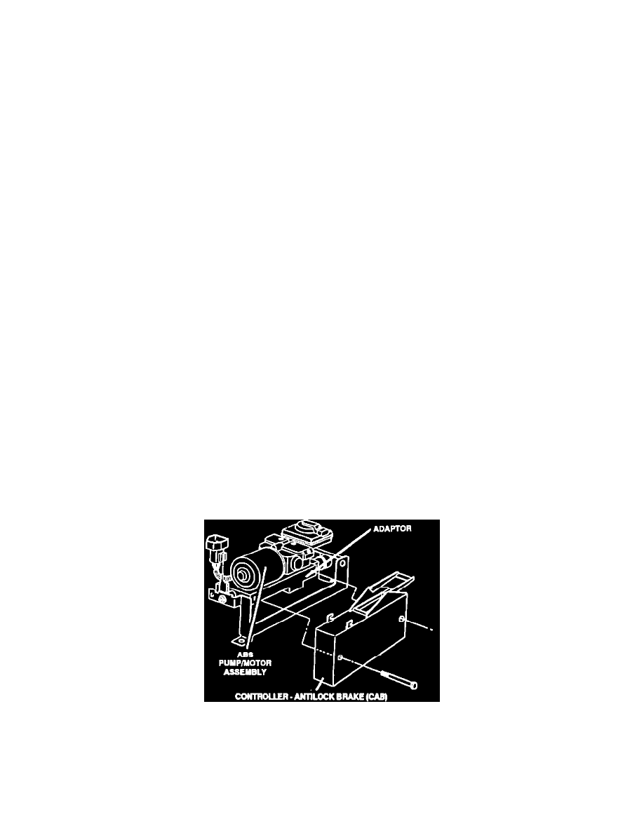
This bulletin involves replacing the Electronic Control Unit (CAB) aluminum adaptor with a polyamid adaptor and installing an adhesive patch.
Check for the presence of an aluminum adaptor between the Electronic Control Unit (CAB) and the housing of the Hydraulic Control Unit (HCU). If an
aluminum adaptor is present, proceed to the repair procedure. If a polyamid plastic adaptor is present, proceed to step 17 in the repair procedure.
NOTE:
FOLLOWING THIS PROCEDURE WILL ENSURE THAT THE BRAKE SYSTEM HYDRAULIC CIRCUITS REMAIN CLOSED. DO NOT
DISCONNECT ANY OF THE BRAKE TUBES ON THE HYDRAULIC UNIT.
1.
With the ignition in the OFF position, disconnect the negative battery cable.
2.
Remove the HCU/CAB heat shield -- two screws one at forward end of shield and one at the rear.
3.
Disconnect 37-way CAB connector, Fluid Level Switch II connector (mini reservoir on HCU) and pump motor connector (on HCU pump).
4.
Remove the three Hydraulic Control Unit (HCU) mounting nuts. One nut is located at the forward end of the unit and two are facing the dash panel
area.