
Vision V6-3.5L VIN F (1997)
-
OTIS then displays whatever display was being viewed when the ignition was turned OFF
There Are 6 Displays:
-
Compass/Temperature
-
Average fuel economy
-
Distance to empty
-
Instantaneous fuel economy
-
Trip odometer
-
Elapsed time
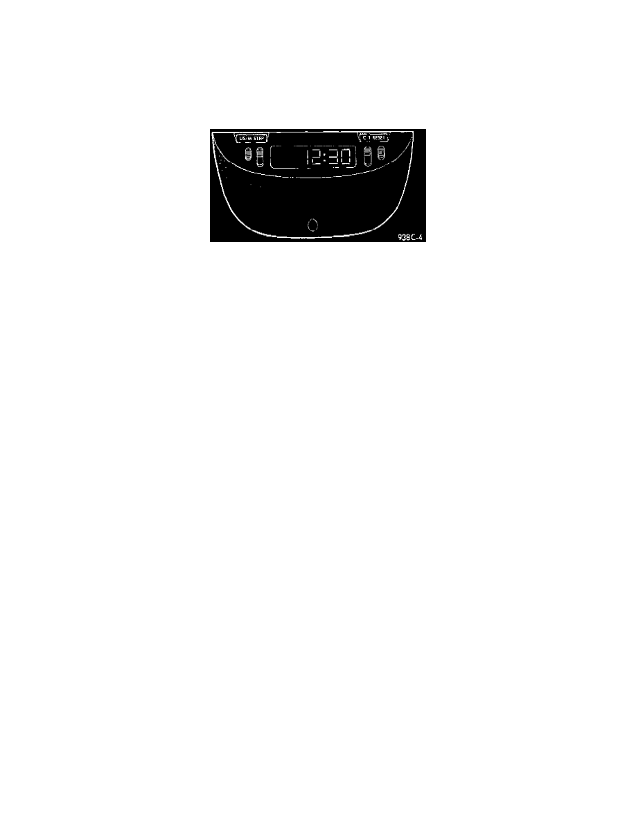
OTIS
There Are 4 Buttons
The buttons operate when the ignition is in the ON position.
-
STEP
-
C/T
-
US/M
-
RESET
Step Button
Pressing the STEP button selects one of the following 5 displays:
-
Average fuel economy
-
Distance to empty
-
Instantaneous fuel economy
-
Trip odometer
-
Elapsed time
C/T (Compass/Temperature) Button
Pressing the C/T button selects the Compass/Temperature display
US/M (English/Metric Measurement) Button
Pressing the US/M button switches the display units between English and Metric readings.
Reset Button
Pressing the RESET button resets the function on the display, provided that function can be reset. The functions which can be reset are
Average fuel economy, Trip odometer and Elapsed time.
The RESET button is also used to set the variance and/or calibrate the compass. Refer to the Variance Procedure and Calibration Procedure.
CIRCUIT OPERATION
The Overhead Travel Information System (OTIS) receives all information across the CCD Bus from various controllers and modules.
Power for the OTIS is supplied by circuit G5. This circuit is protected by a 5 amp fuse located in cavity 14 of the junction block. Power for the
fuse is supplied on circuit A21.
The A21 circuit connects between the ignition switch and the junction block. Circuit A21 is HOT in the START and RUN positions only
Power for the A21 circuit is supplied by circuit A1 from the Power Distribution Center (PDC). This circuit is protected by a 20 amp fuse located
in cavity A of the PDC.
Ground for the OTIS is provided on circuit Z2. This circuit terminates at the Airbag Control Module (ACM) bracket.