
Vision V6-3.5L VIN F (1997)
Brake Fluid Pump Relay: Description and Operation
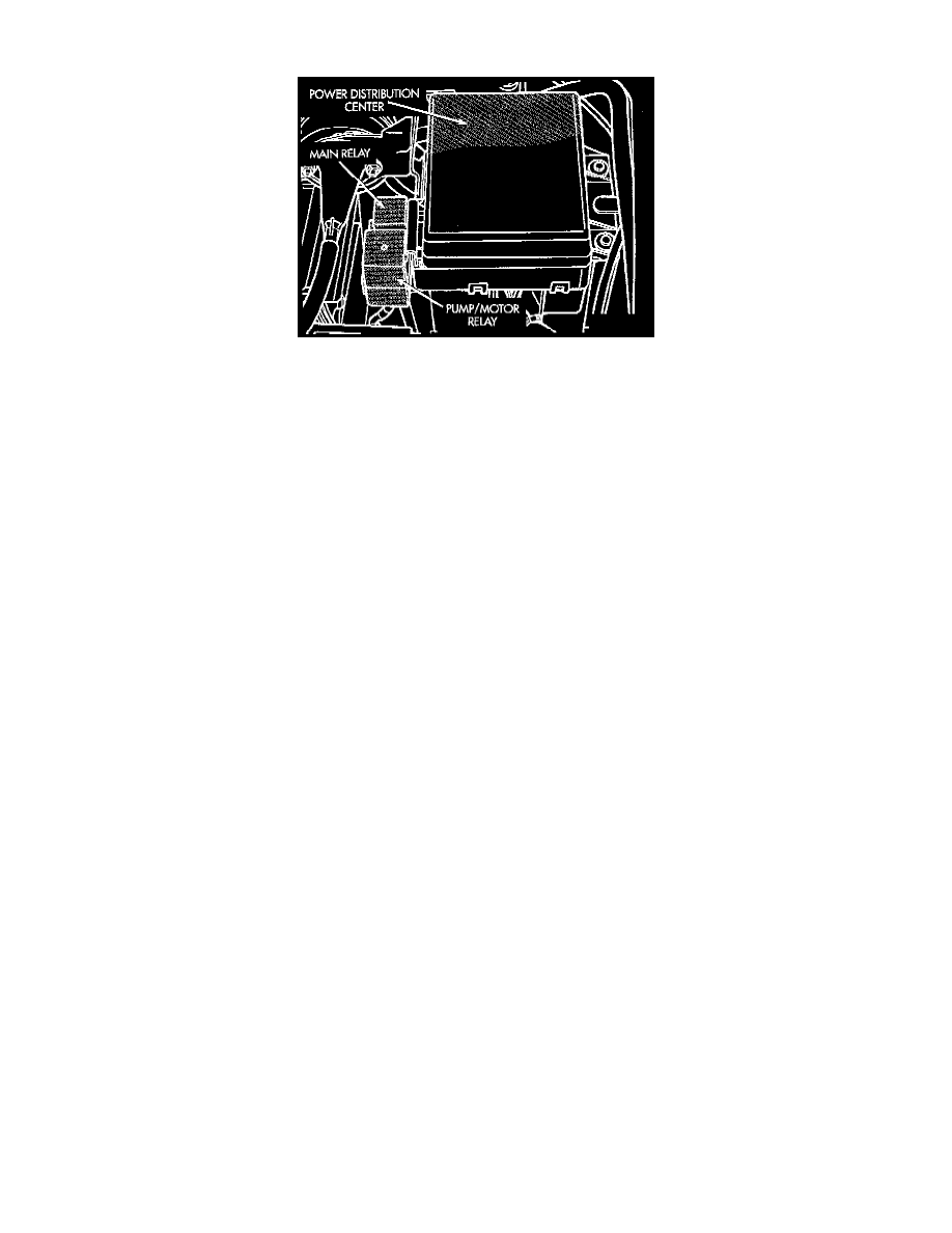
Main Relay And Pump/Motor Relay
OPERATION
The Pump/Motor Relay supplies power to the pump/motor. It is attached to the outside of the Power Distribution Center (PDC). The relay coil is
powered by the Main Relay and the coil ground is controlled by the Controller Antilock Brake CAB. The Pump/Motor Relay is a special four
terminal relay and should not be replaced with a standard relay. If either relay is defective both relays must be replaced. They are serviced as an
assembly.
CIRCUIT OPERATION
The ABS pump motor relay, located on the Power Distribution Center (PDC), is used to control the operation of the pump motor. Power for the
coil side of the relay is supplied by circuit B120. This circuit is HOT when the ABS main relay is energized.
Ground for the coil side of the relay is controlled by the Controller Anti-Lock Brake (CAB) module on circuit B116.
Power for the contact side of the relay is supplied by circuit A10. This circuit is protected by a 40 amp fuse located in cavity C of the PDC.
When the control module grounds circuit B116 the contacts in the relay CLOSE connecting circuits A10 and B82. Circuit B82 connects from the
relay to the pump motor.
The B82 circuit is spliced and provides an input to the CAB for pump motor sense.