
Vision V6-3.5L VIN F (1997)
Radiator Cooling Fan Motor: Description and Operation
DESCRIPTION
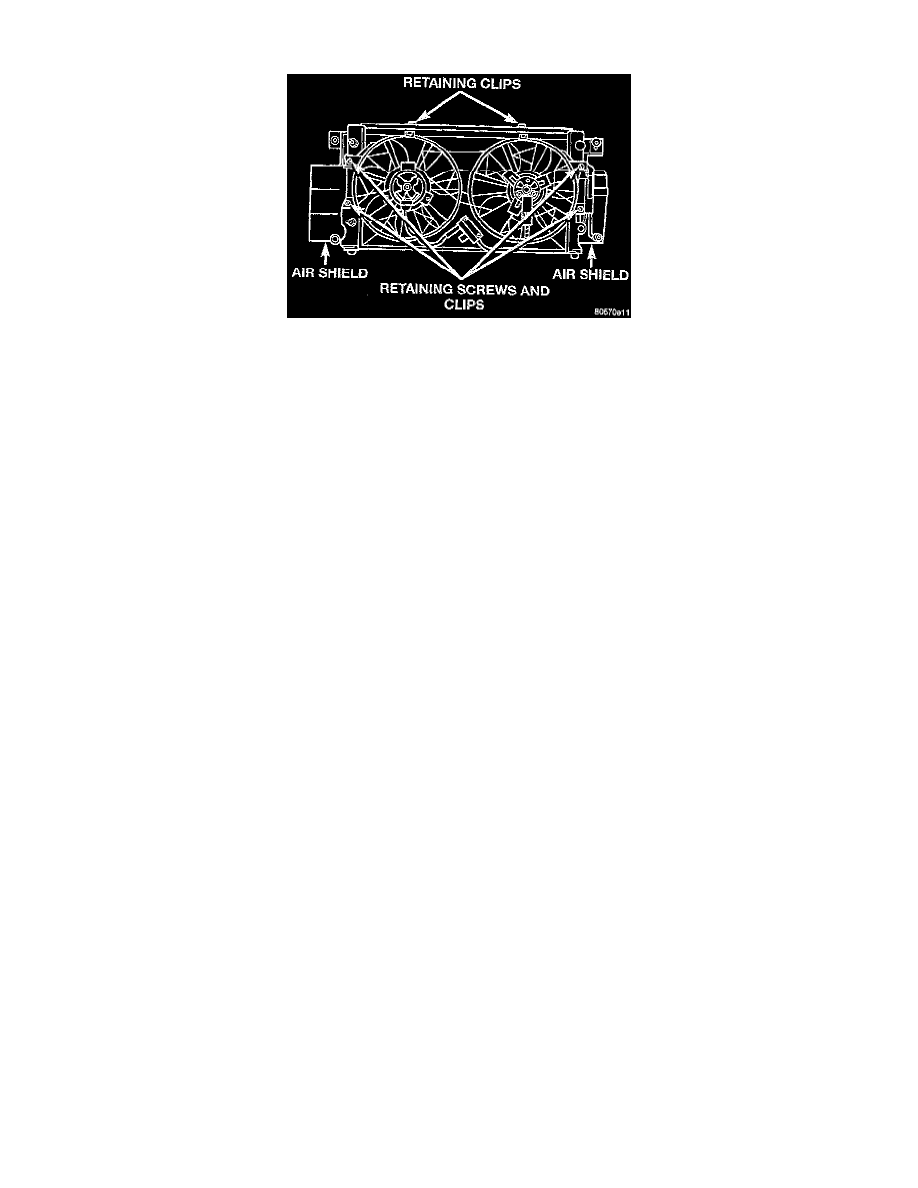
All models use electric motor driven fans. The fan modules include a motor support and shroud. The module is fastened to the radiator by screws
with U-nuts and retaining clips.
OPERATION
The dual fan module is a combination of 2 fans mounted in a one piece shroud which operate at two speeds and are simultaneously activated. The
dual fan system improves engine cooling and air conditioning performance in hot weather and severe driving conditions, while reducing fan noise
and power consumption.
CAUTION: Attempts to reduce high temperature gauge reading by increasing engine speed, at the same vehicle speed, can increase high temperature.
CIRCUIT OPERATION
The radiator fan system uses two relays located in the Power Distribution Center (PDC). One relay is used for LOW speed fan operation and the
other is for HIGH speed operation. The Powertrain Control Module (PCM) controls the operation of the relays depending on engine coolant
temperature and/or A/C operation.
Power for the coil side of both relays is provided on circuit F18. This circuit is protected by a 10 amp fuse located in cavity 20 of the junction
block. Power for the contact side of the relays is provided on circuit A16. This circuit is protected by a 40 amp fuse located in cavity D of the
PDC.
When LOW speed fan operation is required, the PCM grounds circuit C24. This causes the contacts in the relay to CLOSE connecting circuits
A16 and C23. Circuit C23 connects from the relay, and is spliced to the low speed fan motor and the Radio Frequency Interference (RFI)
suppression module. Ground for the motor is provided on circuit Z1, which terminates at the left front frame rail.
When HIGH speed fan operation is required the PCM grounds circuit C27. This causes the contacts in the relay to CLOSE connecting circuits
A16 and C25. Circuit C25 connects from the relay, and is spliced to the high speed fan motor and the RFI suppression module. Ground for the
motor is provided on circuit Z1, which terminates at the left front frame rail.