
Vision V6-3.5L VIN F (1997)
Data Link Connector: Description and Operation
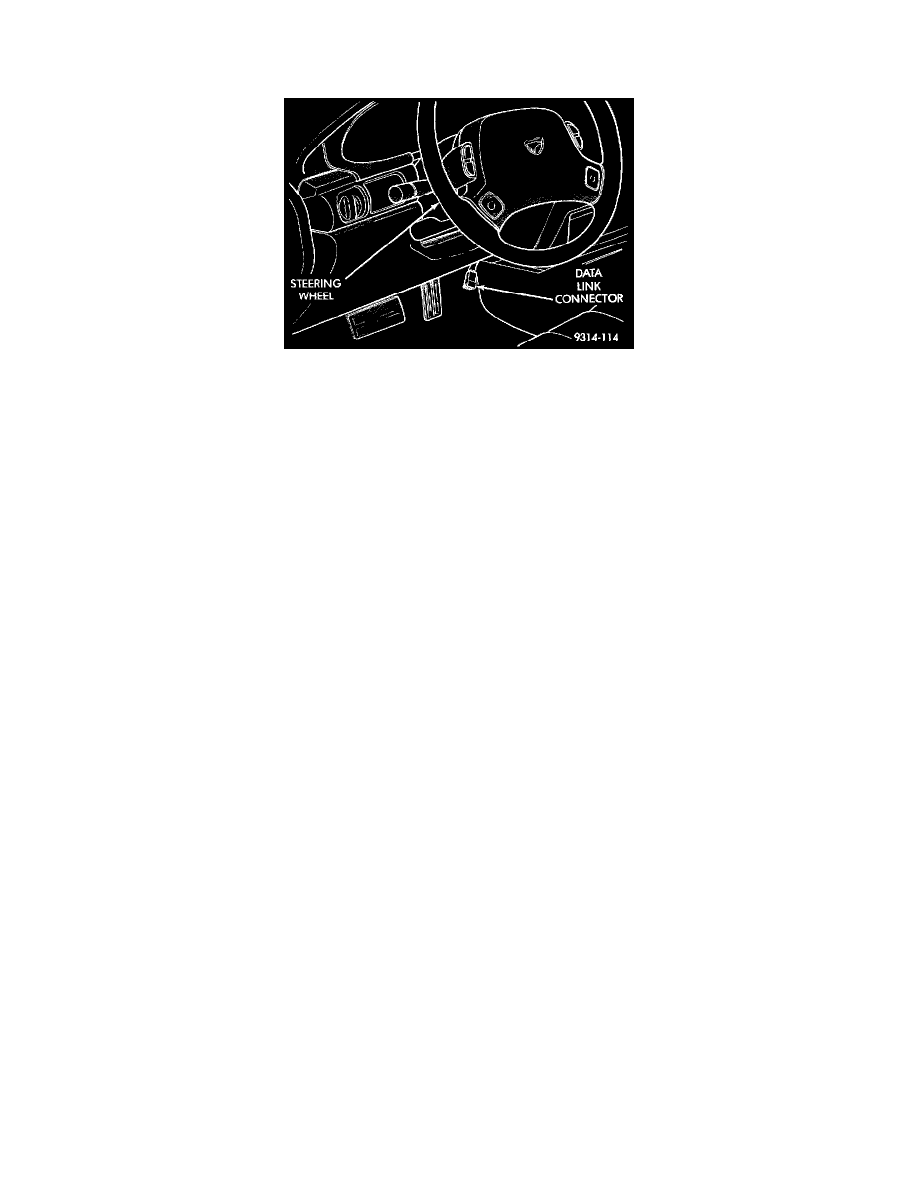
Data Link Connector
PURPOSE
Communication link to Powertrain Control Module (PCM)
Technician can access inputs and memory including:
-
Sensor input values
-
Diagnostic Trouble Codes (DTC's) stored in memory
-
Last deactivation cause (i.e.. speed control last shut off by; speed control switch, brake switch or no crank sensor signal).
Technician can actuate most PCM output devices.
NOTE: Monitoring inputs, reading other memory and actuating output devices can only be accomplished through the use of a scan tool. SEE
TESTING AND INSPECTION.
CIRCUIT OPERATION
Circuit M1 supplies battery voltage to the data link connector. This circuit is protected by a 10 Amp fuse located in cavity 13 of the junction
block. Circuit M1 is the Ignition Off Draw (IOD) circuit and supplies power to the Body Control Module (BCM), radio memory, interior lamps,
power sunroof, and the power antenna.
A twisted pair of wires, circuits D1 and D2, connect to the data link connector and the Powertrain Control Module, cavities 59 and 60. These wires
are connected to the CCD Bus. The CCD Bus is used for diagnosing vehicle components and modules.
Circuits D20 and D21 from the Powertrain Control Module (PCM) connect to the data link connector. Circuit D20 connects to cavity 75 of the
PCM and is the SCI receive circuit. Circuit D21 connects to cavity 65 of the PCM and is the SCI transmit.
Circuit D21 is also spliced and connects to the Transmission Control Module (TCM).
Circuit Z2 is the ground for the universal data link connector. This ground terminates at the Airbag Control Module (ACM) bracket.
Two other circuits also connect to the universal data link connection They are the D6 and D9 circuits. The D6 circuit connects to the TCM and is
used for diagnostics. The D9 circuit is connected to the Remote Keyless Entry (RKE) module and is used for programming the system.