
Vision V6-3.5L VIN F (1997)
Clockspring Assembly / Spiral Cable: Service and Repair
REMOVAL
1. Place the front road wheels in the straight ahead position then:
^
Rotate the steering wheel half turn (180 degrees) to the right (clockwise).
^
Lock column with ignition lock cylinder.
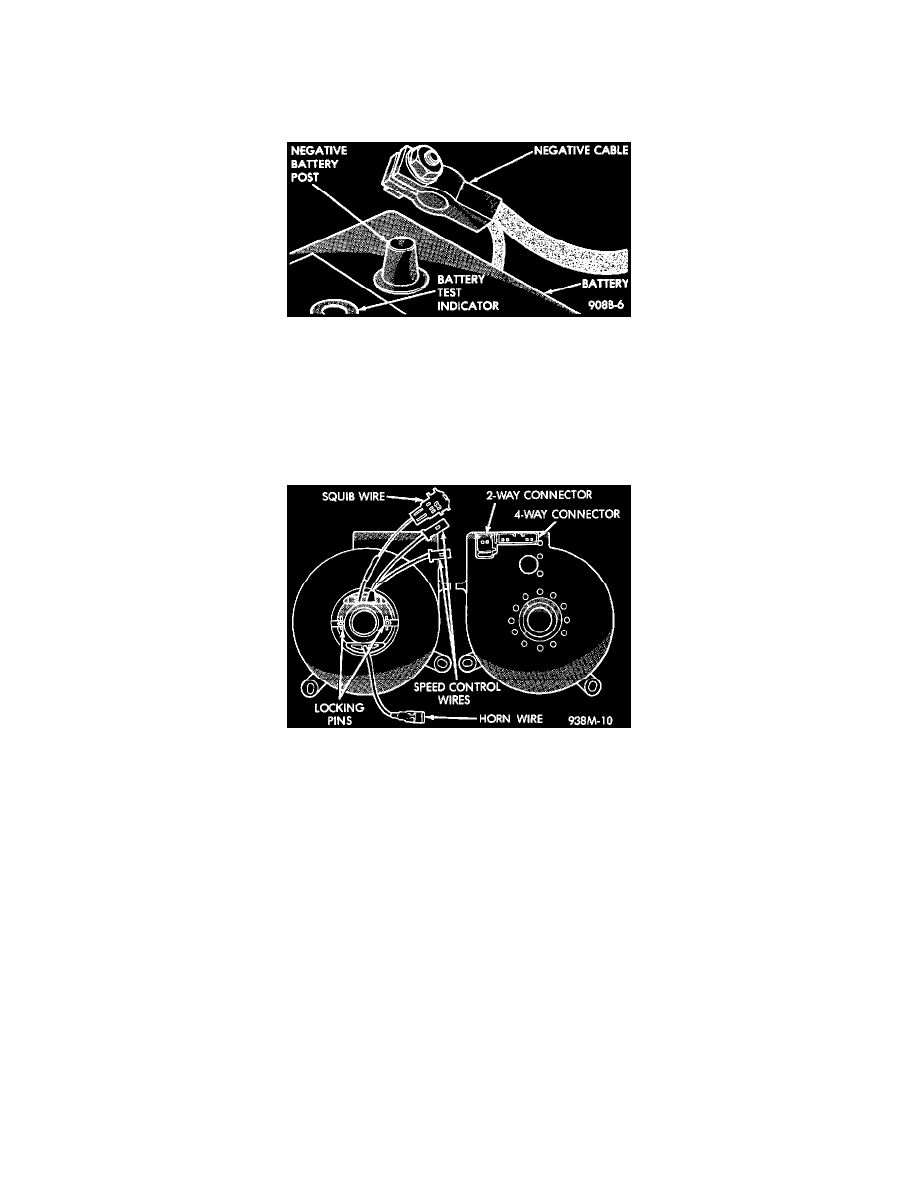
2. Disconnect and isolate the battery negative cable.
3. Wait two minutes for the reserve capacitor to discharge before removing non deployed module.
4. Remove speed control switch mounting screws, switches and disconnect the wire connectors or remove covers.
5. Remove the Driver Airbag Module attaching bolts from the back of steering wheel.
6. Lift module and disconnect the airbag and horn wire connectors.
7. Remove the steering wheel.
8. Remove the tilt wheel release lever.
9. Remove upper and lower steering column shrouds to gain access to clockspring wiring.
10. Disconnect the 2-way and 4-way connectors between the clockspring and the instrument panel wiring harness at the base of the clockspring.
11. Remove the halo light wire from the clip on the side of the clockspring.
12. Remove two mounting screws and pull clockspring assembly from steering shaft. The clockspring cannot be repaired, and must be replaced if
faulty.
INSTALLATION
1. Confirm that:
^
The steering wheel position is a half turn (180 degrees) to the right (clockwise).
^
The column is locked with the ignition cylinder lock.
^
Locate the clockspring on the steering shaft and push down on the rotor until the clockspring is fully seated on the steering column.
^
Fasten clockspring to steering column using the two mounting screws.
^
Tighten the screw near the ignition switch halo light first.
^
Tighten to 2.7 N.m (24 in. lbs.) torque.
2. Connect the clockspring to the instrument panel harness ensure wiring is properly routed. Then check that the connectors, locking tabs are properly
engaged and the halo lamp wire is in position.
3. Install steering column shrouds. Be sure all wires are inside of shrouds.
4. Install the tilt wheel release lever, if equipped.
5. Install steering wheel ensuring the flats on hub align with the clockspring. Tighten steering wheel nut to 61 N.m (45 ft. lbs.) torque. Pull the
yellow horn lead through the smaller round hole. Pull the airbag and speed control leads through the larger slot. Ensure leads do not get pinched
under the steering wheel.
6. Route speed control wires under and behind the airbag module mounting tabs.
7. Connect the yellow horn lead wire and the airbag lead wire to the airbag module.
8. Install the airbag module and tighten bolts to 9 N.m (80 in. lbs.) torque.
9. Connect the speed control wires to the switches and install switches. Tighten screws to 1.5 N.m (13 in. lbs.) torque.