
Vision V6-3.5L VIN F (1997)
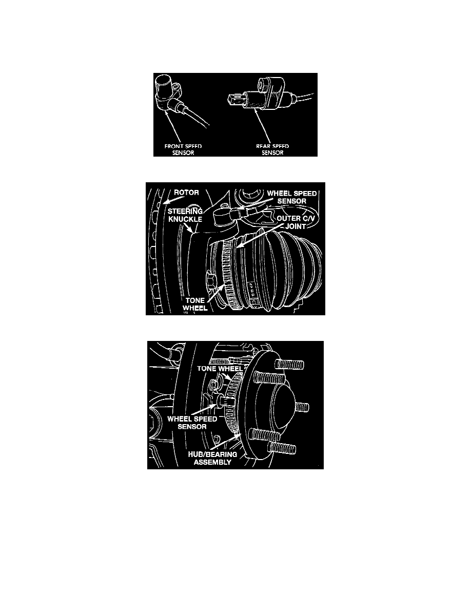
Wheel Speed Sensor: Description and Operation
GENEERAL INFORMATION
One wheel speed sensor WSS is located at each wheel and sends a small AC signal to the Controller Antilock Brake CAB. This voltage is
generated by magnetic induction when a toothed sensor ring (tonewheel) passes by a stationary magnetic sensor WSS. The CAB converts the AC
signals into digital signals for each wheel.
Wheel Speed Sensors
Front Wheel Speed Sensor And Tone Wheel
Rear Wheel Speed Sensor And Tone Wheel
The front wheel speed sensor is attached to a boss in the steering knuckle. The tonewheel is an integral part of the front axle shaft outer C/V joint.
The rear speed sensor is mounted in the caliper adapter plate and the rear tonewheel is an integral part of the rear rotor hub. The wheel speed
sensor air gap is NOT adjustable. The correct wheel speed sensor air gap is from 0.52 to 1.64mm for the front sensors, and from 0.45 to
1.2lmm for the rear sensors. All wheel speed sensors have a resistance between 800 and 1400 ohms. The four wheel speed sensors are serviced
individually. The front tonewheels are serviced as an assembly with the outer C.V Joint Housing. The rear tonewheels are serviced as an assembly
with the rotor hub.
OPERATION
Correct ABS system operation is dependent on the wheel speed signals from the wheel speed sensors. The wheels and tires should all be the same
size and type to generate accurate signals. In addition, the tires should be inflated to the recommended pressures for optimum system operation.
Variations in wheel and tire size or significant variations in inflation pressure can produce inaccurate wheel speed signals. However, the system