
Vision V6-3.5L VIN F (1997)
Alignment: Service and Repair
Caster and Camber Adjustment
GENERAL INFORMATION
Front wheel Caster and Camber settings on this vehicle are determined at the time the vehicle is designed. This is done by determining the precise
mounting location of the vehicle's suspension components throughout the design and assembly processes of the vehicle. This is called a Net Build
vehicle and results in no normal requirement to adjustment the Caster and Camber after a vehicle is built or when servicing the suspension
components. Thus Caster and Camber are not normally considered an adjustable specification when performing an alignment on this vehicle.
Though Caster and Camber are not adjustable they should be checked during the alignment procedure to ensure they meet the manufacturers
specifications.
If a vehicle has a drift or lead condition, and it is determined that the drift or lead is not caused by road conditions, and front camber is not within
specifications it can be adjusted using the following camber adjustment procedure.
If camber does not meet required specifications, the vehicles suspension components should be inspected for any signs of damage or bending and
the vehicle ride height should be checked to verify it is within required specification. This inspection must be done before performing the camber
setting procedure.
CAUTION: Do not attempt to adjust the vehicles Caster or Camber by heating, bending or by performing any other modification to the vehicle's
front suspension components.
CHECK
1. Correctly position the vehicle on an alignment rack. Install all required alignment equipment on the vehicle, per the alignment equipment
manufacturers specifications.
NOTE: Prior to reading each alignment specification, front and rear of vehicle should be jounced an equal number of times. Induce jounce (rear
first then front) by grasping center of bumper and jouncing each end of vehicle an equal number of times. Bumper should always be released when
vehicle is at the bottom of the jounce cycle.
2. Correctly jounce vehicle and then read the vehicle's current front and rear alignment settings. Compare the vehicle's current alignment settings to
the vehicle specifications for camber, caster and Toe-in. If front and rear camber readings are within required specifications proceed to Front
Wheel Toe Adjustment for the Toe adjustment procedure if required. If Camber readings are not within specifications refer to Step 1 in the
following front camber adjustment procedure.
CAMBER ADJUSTMENT PROCEDURE
1. If the front camber readings obtained are not within the vehicle's specifications, use the following procedure to provide camber adjustment.
2. Verify that the strut and steering knuckle are not bent or otherwise damaged. If either component is bent or show other signs of damage, replace
required component(s) and check the camber setting again.
3. If no component is bent or damaged, use the following procedure for modifying the strut clevis bracket and adjusting the camber setting.
4. Raise front of vehicle until tires are not supporting the weight of the vehicle. Remove wheel and tire assembly from the location on the vehicle
requiring the strut clevis modification.
CAUTION: When removing the steering knuckle from the strut clevis bracket, do not put a strain on the brake flex hose. Also, do not let the
weight of the steering knuckle assembly be supported by the brake flex hose when removed from the strut assembly. If necessary use a wire hanger
to support the steering knuckle assembly or if required remove the caliper from the steering knuckle.
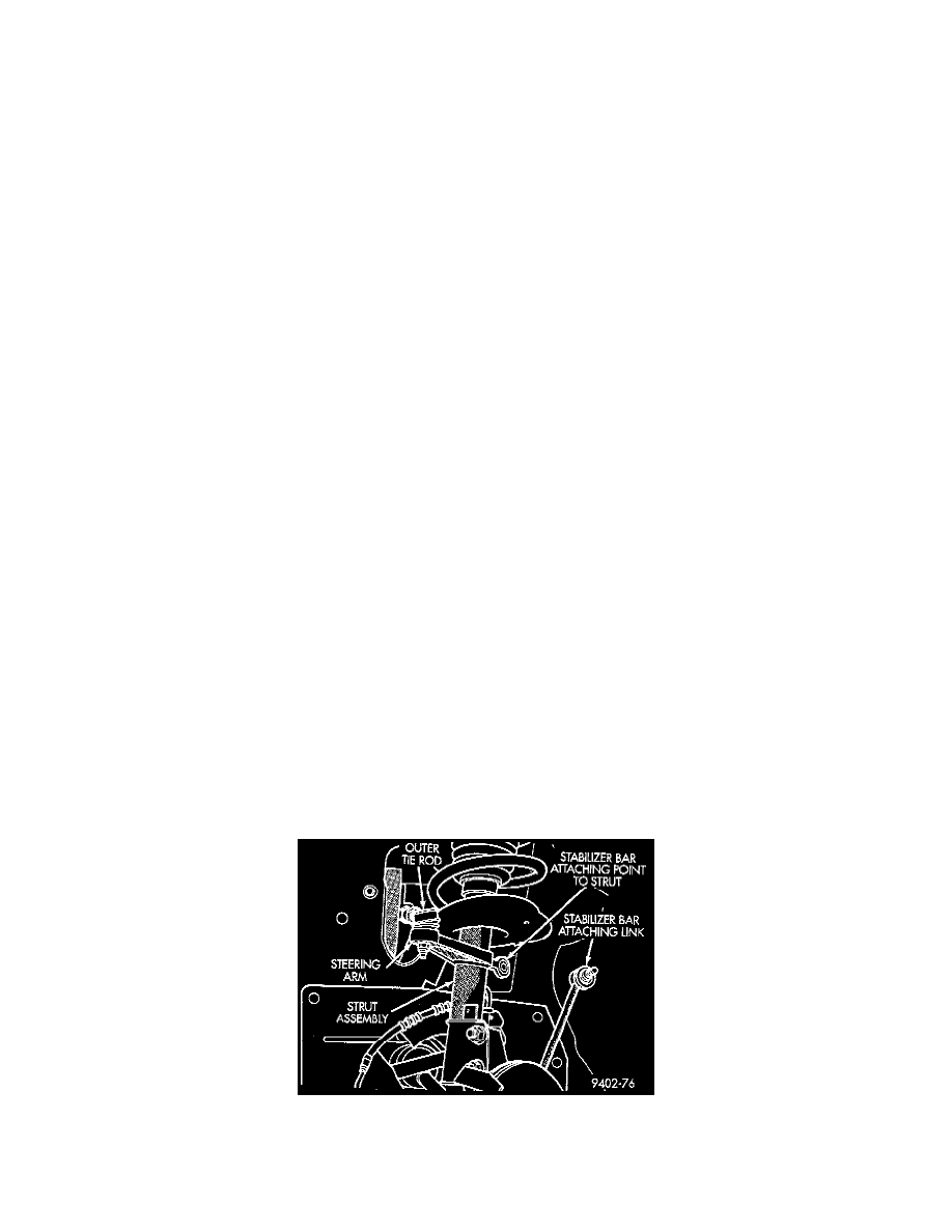
5. Remove the stabilizer bar attaching link from the strut.