
X1/9 L4-1498cc 15L Positive Crankcase Ventilation System Overview
Positive Crankcase Ventilation: Description and Operation
Carbureted Models
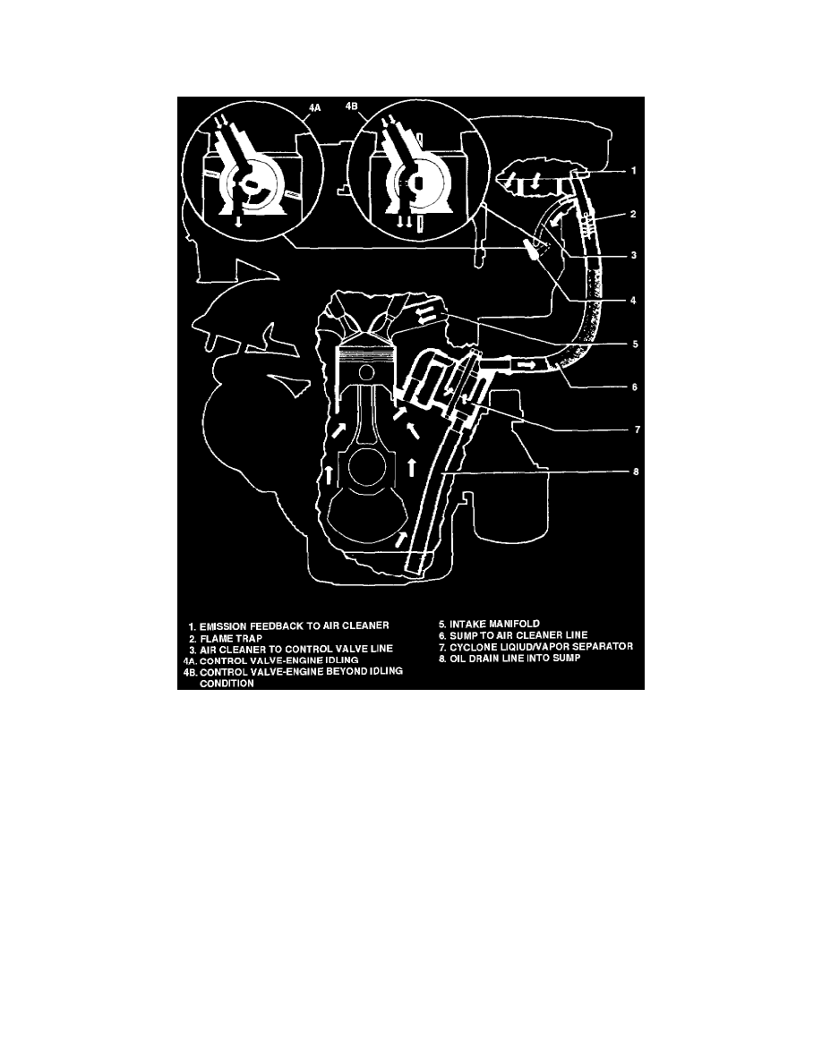
Fig. 001 - Crankcase Control System
This system returns blow-by gasses both to the intake manifold and to the carburetor air cleaner, Fig. 1. A valve controlled by the carburetor
throttle shaft conducts crankcase blow-by gasses into the intake manifold. Blow-by gasses are ducted from the crankcase through a liquid/vapor
separator and a tube which is connected to the carburetor air cleaner. The vacuum line from the control valve is connected to the tube at the air
cleaner.
When the throttle is closed, blow-by gasses are drawn into the intake manifold through a calibrated orifice in the control valve, Fig. 1. As the
throttle opens, the size of the orifice increases, increasing the amount of vacuum applied to the system. At full throttle, manifold vacuum is
insufficient to draw all of the blow- by gasses into the manifold. The excess is drawn into the clean side of the air cleaner.
Fuel injected Models