
Aerostar 2WD V6-182 3.0L (1995)
Cruise Control Switch: Testing and Inspection
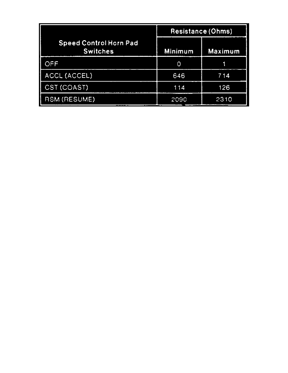
Speed Control Switch Assembly Voltage Specifications.
1. Disconnect 6-pin connector at amplifier, then connect multimeter positive lead to circuit 151 (LB/BK) at amplifier connector.
2. Connect negative lead to amplifier ground, then observe resistance reading while turning the steering wheel 1/4 turn left and right and depressing
speed control actuator switches indicated. If resistance measurements are within chart specifications, switches and wiring are serviceable. If
resistance readings are not within the chart specifications, proceed to following step.
3. Disconnect speed control wiring harness at steering column connector, then repeat previous resistance checks at steering column connector.
4. If resistance measurements are within the chart specifications, repair wiring between steering column connector and amplifier. If resistance
measurements are not within chart specifications, proceed to following step.
5. Carefully remove air bag module.
6. Disconnect speed control switch harness at air bag sliding contact, then repeat previous resistance checks at switch harness connector.
7. If resistance checks are within the specifications, replace air bag sliding contact or repair wiring between air bag sliding contact and steering
column connector. If resistance checks are not within the charts specifications, replace steering wheel harness or speed control switches.