
Aerostar 2WD V6-182 3.0L (1995)
Mass Air Flow (MAF) Sensor: Description and Operation
Mass Air Flow Sensor
PURPOSE
The Mass Air Flow (MAF) sensor measures the total volume and mass of air flowing into the engine. This value is one of the major factors used
by the Powertrain Control Module (PCM) in determining the fuel injection base pulse width and ignition timing advance.
CONSTRUCTION
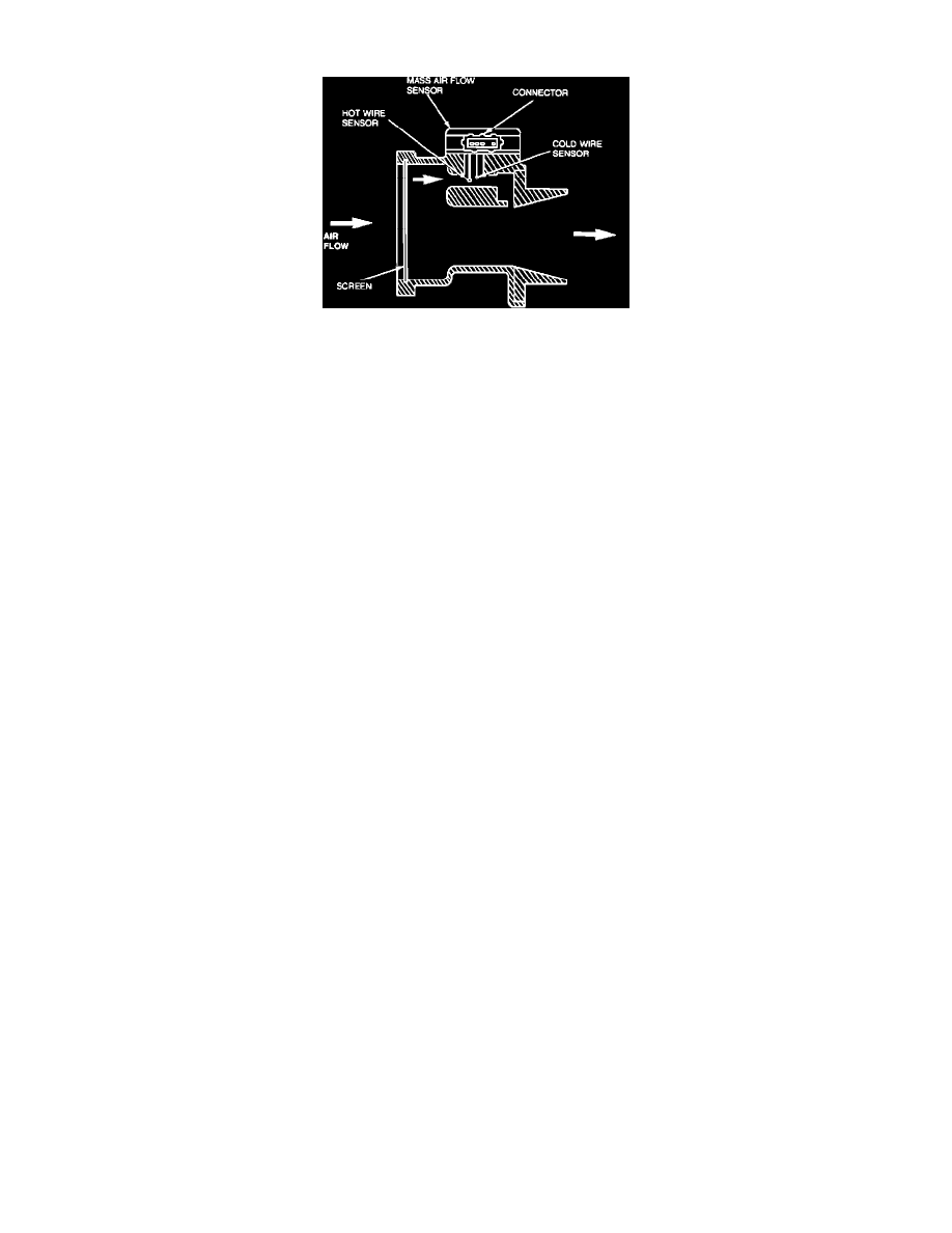
The MAF sensor is located directly in the air flow path between the air cleaner housing and the throttle body. The sensor is designed and located
such that all air entering the intake manifold must flow through it. Located in the MAF sensor directly in the airstream are two platinum wires, a
hot wire heated by electrical current and a cold reference wire. The MAF sensor uses the air flow across these wires to calculate its output.
OPERATION
The MAF sensor operates on the principle that if the hot wire is maintained at a constant temperature above ambient, the thermal loss exhibited by
the hot wire is proportional to the total mass of air flowing across it.
The sensor maintains the hot wire exactly 200°C (392°F) hotter than the reference (cold) wire. The MAF sensor then measures the amount of
electrical current required to maintain this temperature difference and converts this value to an analog DC voltage. This output varies directly with
the mass air flow rate and ranges from 0.5 to 4.5 volts.
RELATED DIAGNOSTIC TROUBLE CODES
DTC 129 - Insufficient MAF sensor output change during the dynamic response (snap throttle) test.
DTC 157 - MAF sensor output went below the minimum value of 0.4 volts (continuous memory code).
DTC 158 - MAF sensor output went above the maximum value of 4.5 volts (continuous memory code).
DTC 159 - MAF sensor output was measured out of range during a self-test, >0.7 volts during the Key On Engine Off (KOEO) test and not
between 0.2-1.5 volts during the Key On Engine Running (KOER) test.
DTC 184 - MAF sensor output is higher than expected.
DTC 185 - MAF sensor output is lower than expected.
Note: DTC 184, 185 were intended to detect in-range failures of the MAF sensor. The PCM compares information from the Mass Air Flow
(MAF) sensor, throttle position sensor, and fuel injection pulse width. If any one value appears to be out of line with the other two an in-range
trouble code will be set.