
Aerostar 2WD V6-182 3.0L (1995)
Throttle Position Sensor: Description and Operation
PURPOSE
The Throttle Position (TP) sensor is a rotary potentiometer that determines throttle plate angle. The Powertrain Control Module (PCM)
determines operating modes from the TP signal. These are:
-
Closed throttle, idle or deceleration
-
Part throttle, cruise or moderate acceleration
-
Wide open throttle, maximum acceleration, dechoke on crank and A/C cutout
-
Throttle angle rate, acceleration pump type function
-
Transmission shift schedule
CONSTRUCTION
The TP sensor is mounted on the throttle body and is directly linked to the throttle shaft. The TP sensor is composed of a wiper arm that moves
along a curved resistor.
OPERATION
The TP sensor measures travel of the throttle shaft to produce a continuously variable output signal proportional to the throttle plate position.
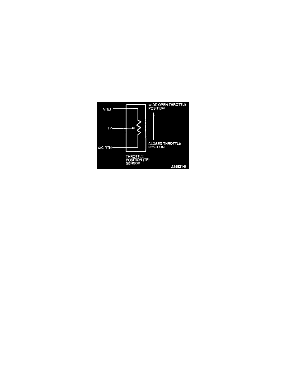
Throttle Position Sensor Schematic
The potentiometer functions as a voltage divider. A 5.0 volt reference signal is applied to one end (VREF) of a curved resistance material, with the
other end grounded along the SIG RTN circuit.
The TP sensor output signal is taken off a wiper arm (mechanically linked to the throttle shaft) that travels along the entire length of the curved
resistor
At closed throttle the TP wiper arm is nearer the ground side of the resistor resulting in a lower output, 0.6 volts at 0% throttle angle.
At wide open throttle the TP wiper arm is nearer the reference voltage side of the resistor resulting in a higher output, 4.5 volts at 85% throttle
angle.
RELATED DIAGNOSTIC TROUBLE CODES
DTC 121 - TP sensor output is out of the self-test range.
DTC 122 - TP sensor output is below the minimum self-test value.
DTC 123 - TP sensor output is above the maximum self-test value.
DTC 124 - TP sensor output is higher than expected.
DTC 125 - TP sensor output is lower than expected.
Note: DTC 124, 125 were intended to detect in-range failures of the TP sensor. The PCM compares information from the Mass Air Flow (MAF)
sensor, TP sensor, and fuel injection pulse width. If any one value appears to be out of line with the other two an in-range trouble code will be set.