
Aerostar 2WD V6-182 3.0L (1995)
12.
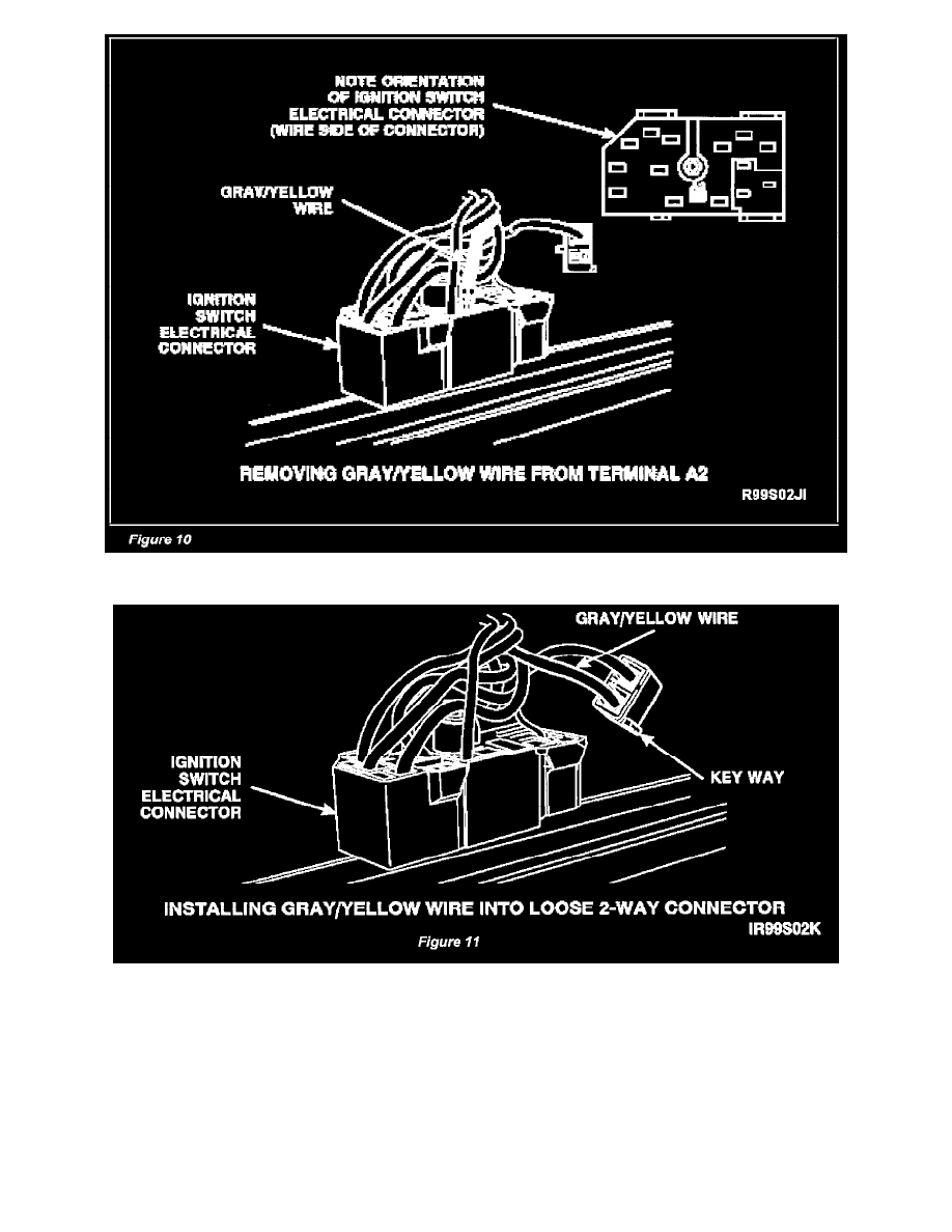
Remove the gray/yellow wire, circuit 687, from terminal A2 of the ignition switch electrical connector. See Figure 10.
13.
Install the gray/yellow wire, circuit 687, into the loose, 2-way connector in the slot next to the key way. See Figure 11.
14.
Install the ignition switch electrical connector wiring shield and terminal locking plate.
15.
On manual transmission equipped vehicles, locate the unused brake shift lock solenoid electrical connector within the ignition switch wiring
harness (under the paper tape). Access the electrical connector by tearing the paper tape (using fingers) on the wiring harness approximately 30
mm (1 inch) from the back of the ignition switch connector.