
Aerostar 2WD V6-182 3.0L (1995)
9.
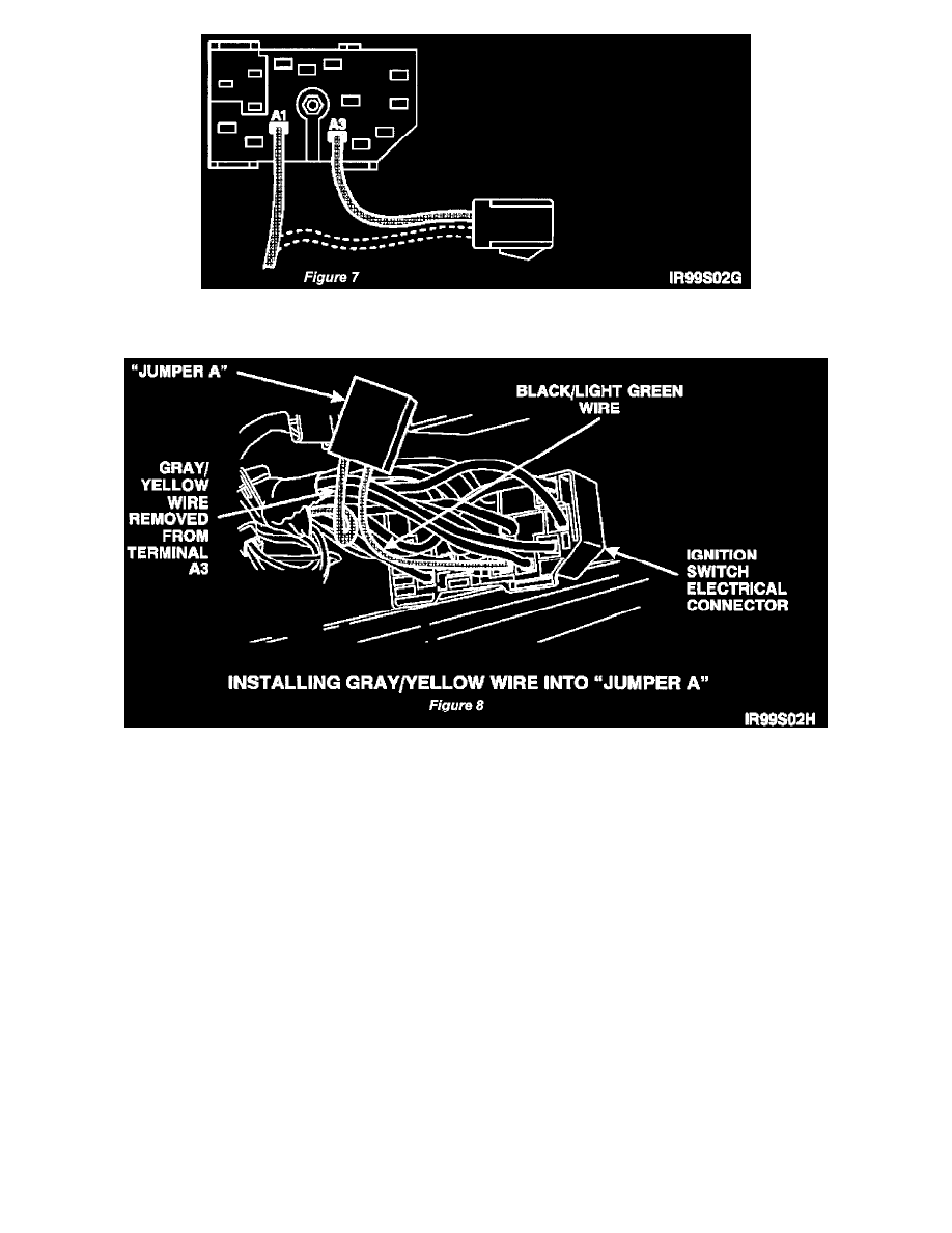
Remove the vehicle wiring harness black/light green wire from jumper A and install it into terminal A1 of the ignition switch electrical connector.
See Figure 7.
10.
Install the gray/yellow wire, circuit 687, previously removed from terminal A3 of the ignition switch electrical connector into the open terminal in
jumper A. See Figure 8.
11.
Connect jumper A electrical connector.
12.
Install the ignition switch electrical connector wiring shield and terminal locking plate.
13.
Install the ignition switch electrical connector. Tighten the retaining screw securely.
14.
Connect the battery negative cable.
15.
Start the engine and verify modification as follows:
^
Turn the blower motor to HIGH.
^
Turn the radio on.
^
On vehicles equipped with automatic transmission, check the brake shift interlock system by trying to shift from Park to any other gear without
depressing the brake pedal.
NOTE:
If any of the above components were working before the modification and are not working now, repeat the service procedure.
16.
Turn the ignition key to the accessory position, then turn the blower motor to HIGH. If the blower motor operates in the accessory position, repeat
the service procedure.