
Aerostar 2WD V6-183 3.0L (1991)
Control Arm: Service and Repair
Front
UPPER ARM
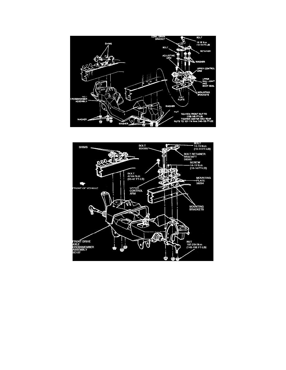
Fig. 5 Upper Control Arm Assembly And Mounting Bracket Replacement. 2WD
Fig. 6 Upper Control Arm Assembly And Mounting Bracket Replacement, 4WD
1.
On 4 x 2 models, remove spindle as outlined previously.
2.
On 4 x 4 models, remove steering knuckle as outlined in STEERING KNUCKLE AND BALL JOINT (FWD).
3.
On all models, remove cowl drain bracket retaining bolt, then bracket and retainer plate, Figs. 5 and 6.
4.
Scribe marks on flat plate where control arm brackets are positioned, then remove front mounting bracket to flat plate retaining bolt.
5.
Working from beneath frame rail, remove control arm mounting bracket to frame rail retaining nuts and bolts. To facilitate bolt removal, swing
control arm aside and allow bolts to drop downward.
6.
Remove upper control arm, ball joint, mounting brackets and adjusting arm as an assembly, then separate control arm from adjusting arm, noting
number and position of adjusting shims.
7.
Reverse procedure to install. Ensure that mounting bracket to flat plate scribe marks are properly aligned. It is imperative that the
mounting bracket to frame rail retaining nuts and bolts be tightened to specifications, since this is the critical joint of the front chassis
area. Ensure to lubricate these nuts and bolts before assembly to ensure accurate torque readings.
LOWER ARM
1.
Remove coil spring as outlined previously.