
Aerostar 2WD V6-245 4.0L (1990)
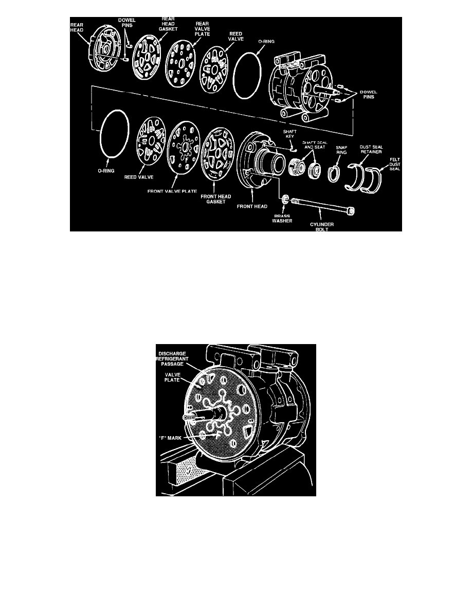
Fig. 19 Disassembled view of compressor.
10.
Remove rear head, head gasket, rear valve plate, reed valve and dowel pins from compressor,
Fig. 19.
11.
Remove front head, head gasket, front valve plate, reed valve and dowel pins from compressor,
Fig. 19.
Installation
1.
Inspect cylinder bores, valve plates and reed plates for scratches, corrosion or other signs of damage or wear. Replace compressor if any of these
conditions exist.
2.
Install two dowel pins in front and rear cylinder assembly.
3.
Lubricate O-ring and install on front and rear cylinder head assembly.
4.
Lubricate front and rear reed valve with clean refrigerant oil and install them on cylinder assembly.
Fig. 20 Compressor front valve plate installation
5.
Lubricate front valve plate (marked with an ``F'') and install on cylinder assembly.
The ``F'' mark must be showing when valve plate is
installed, Fig. 20.
6.
Lubricate rear valve plate (marked with an ``R'') and install on cylinder assembly.
The ``R'' must be showing when valve plate is installed.
7.
Lubricate front and rear head gaskets and install them in proper position on cylinder assemblies.
8.
Install front and rear heads on cylinder assembly, aligning dowel pins with dowel pin holes in cylinder head.