
Aerostar 2WD V6-245 4.0L (1990)
Malfunction Indicator Lamp: Description and Operation
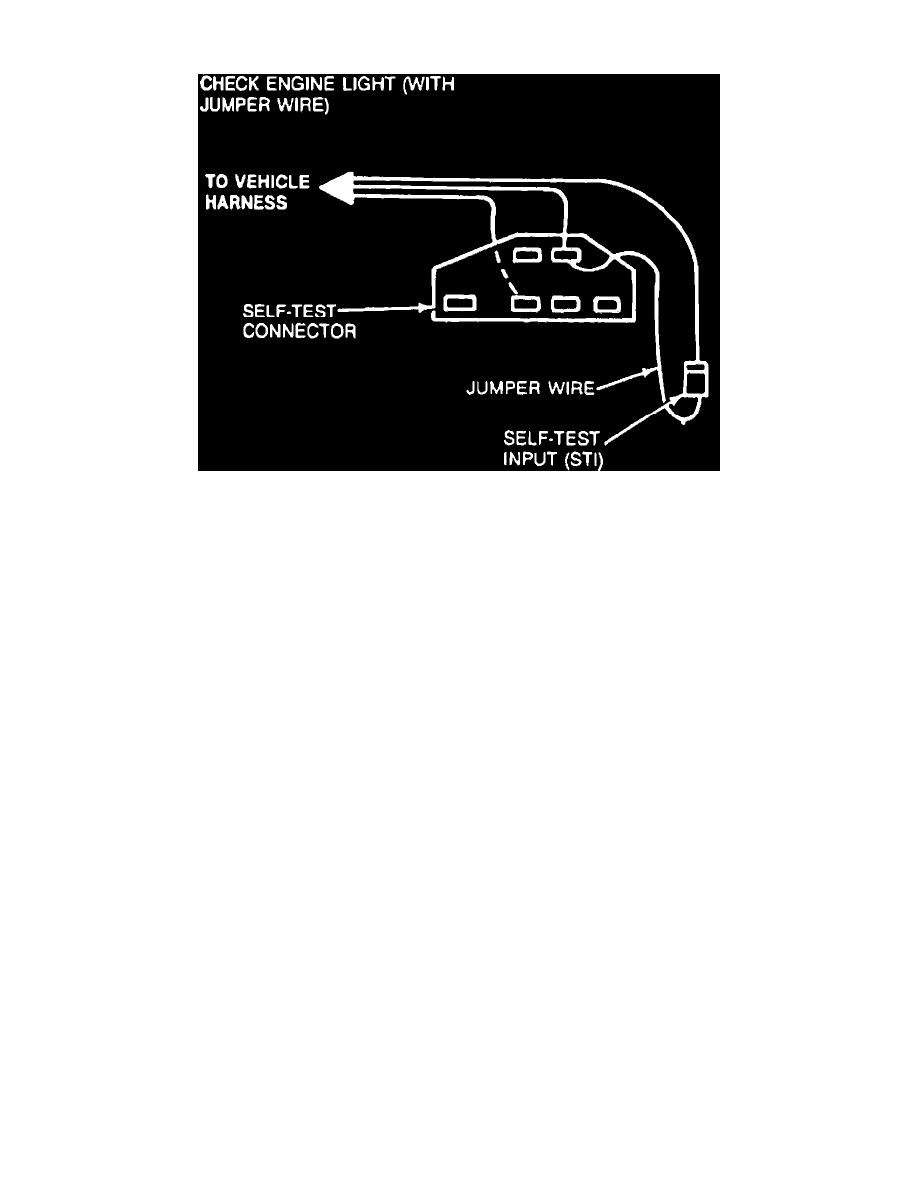
Fig. 1 Jumper wire connections for resetting Check Engine Lamp.
1985-90 Models w/EEC-IV
This lamp will be illuminated when the ignition switch is placed in the On position. After engine is started the lamp should go off, unless a problem has
been detected by the EEC-IV system. After diagnosis and repair, the Check Engine/MIL lamp will automatically reset when stored codes are cleared
from the EEC-IV system memory. After diagnosis and repair, EEC-IV memory may be cleared of stored codes as follows:
1.
With ignition switch in the Off position, connect a jumper wire between Self Test and Self Test Input (STI) connectors, Fig. 1.
On Aerostar, the Self Test and STI connectors are gray in color and are located on lefthand fender apron, near the Electronic Engine Control (EEC)
relay. On Bronco and F Series, the Self Test and STI connectors are located in the area of the EEC system charcoal canister. On Bronco II and
Ranger, the Self Test connector and STI connector are red in color and they are both located on the righthand fender apron near the Electronic Engine
Control (EEC) relay. On E Series, the Self Test and the STI connectors are located on the righthand fender apron in the area of the MAP sensor and
starter motor relay.
2.
Position ignition switch in On position, then disconnect jumper wire from test connector terminals. Disconnect jumper as soon as Check Engine
lamp starts flashing.