
Aerostar 2WD V6-245 4.0L (1990)
Temperature Gauge: Description and Operation
CONSTANT VOLTAGE REGULATOR GAUGE SYSTEM (CVR)
This temperature indicating system consists of a sending unit, located on the cylinder head, electrical temperature gauge and an instrument voltage
regulator. As engine temperature increases or decreases, the resistance of the sending unit changes, in turn controlling current flow to the gauge. When
engine temperature is low, the resistance of the sending unit is high, restricting current flow to the gauge, in turn indicating low engine temperature. As
engine temperature increases, the resistance of the ending unit decreases, permitting an increased current flow to the gauge, resulting in an increased
temperature reading.
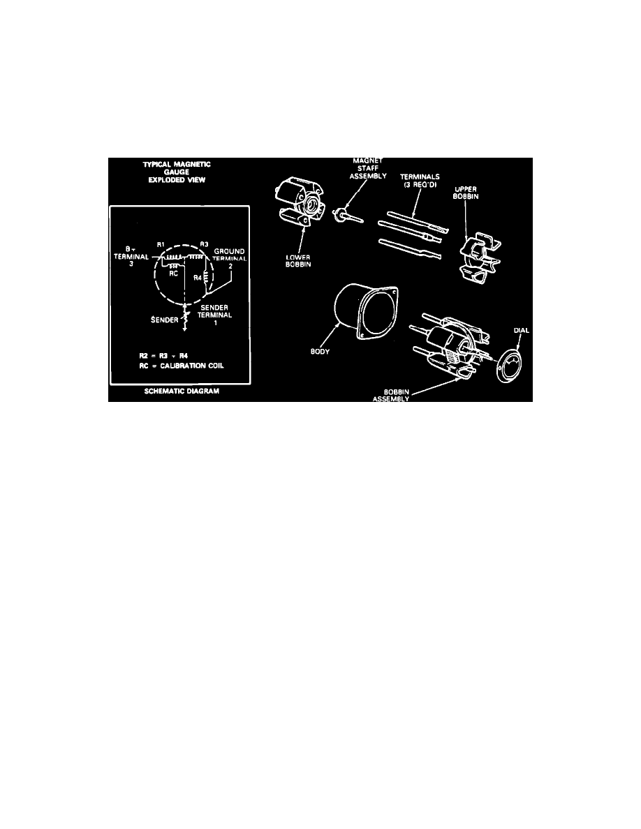
MAGNETIC GAUGE SYSTEM
Fig. 8 Magnetic Guage
The magnetic gauge movement consists of three primary coils, one of which is wound at a 90° angle to the other two. The coils form a magnetic field
which varies in direction according to the variable resistance of the sender unit which is connected between two of them. A primary magnet which is
attached to a shaft and pointer rotates and aligns to this primary field resulting in pointer position. The bobbin/coil assembly is pressed into a metal
housing which is attached to the instrument cluster, Fig. 8. These gauges require no adjustments, calibrations or maintenance. This gauge system does
not use an IVR.