
Aerostar 2WD V6-245 4.0L (1990)
Sector Shaft: Service and Repair
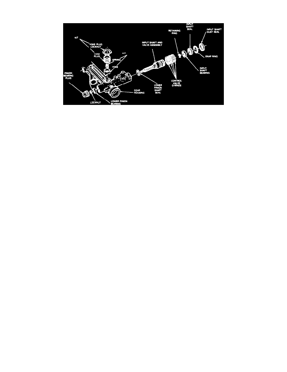
Fig. 2 Input Shaft And Valve Assembly
DISASSEMBLY
1.
Thoroughly clean input shaft valve housing, yoke locknut, plug and pinion bearing plug.
2.
Install steering gear in suitable holding fixture. Do not remove external pressure lines unless they are leaking or damaged. If lines are
removed, new Teflon seals must be installed.
3.
Using locknut wrench tool No. T78P-3504-H or equivalent, loosen yoke plug locknut, then yoke plug, Fig. 2.
4.
Remove pinion bearing plug.
5.
Install pinion shaft torque adapter tool No. T74P-3504-R or equivalent on input shaft and remove pinion bearing locknut while holding input shaft.
Do not allow rack to reach full travel when loosening or tightening locknut.
6.
Using suitable tool, Pry input shaft dust seal from housing, being careful not to damage valve housing surfaces.
7.
Remove snap ring, located beneath dust seal, from housing.
8.
Install puller tool No. T78P-3504-B or equivalent, on input shaft and tighten nut on tool to remove input shaft and valve assembly, together with
input shaft seal and bearing, from housing.
9.
To remove lower pinion shaft seal, insert seal remover tool No. T78P-3504-E2 and spacer collar tool No. T86P-3504-J or equivalents, until it
bottoms, then hold large nut and tighten small nut on tool until expander fully tightens.
10.
Install slide hammer tool No. T50T-100-A or equivalent, in rear of seal remover tool No. T78P-3504-EZ or equivalent, then pull lower pinion
shaft seal from housing.
11.
Inspect pinion bearing, removing only if replacement is necessary.
12.
Remove O-ring seals only if replacement is necessary.
ASSEMBLY
1.
If pinion bearing was removed, place lower pinion bearing on bearing installation tool No. T78P-3504-G, or equivalent and position bearing and
tool in lower housing.
2.
Support housing with wooden block and drive pinion bearing into housing until it is seated against shoulder in bore.
3.
Coat lower pinion oil seal with suitable lubricant, place seal on installation tool with seal lip facing toward tool, support housing on clean flat
surface and drive seal until it is seated against shoulder.
4.
If O-ring seals were removed, proceed as follows:
a.
Mount pinion end of valve assembly in suitable vise.
b.
Lubricate mandrel tool No. T75L-3517-A1 or equivalent with suitable lubricant and install tool over valve assembly, then slide one valve
sleeve O-ring over tool.
c.
Slide ring pusher tool No. T75L-3517-A2 or equivalent over mandrel and push down rapidly to force O-ring down ramp into fourth groove of
valve sleeve.
d.
Repeat above step three more times, adding one spacer under mandrel each time.
e.
Apply suitable lubricant to sleeve and O-rings.
f.
Install one spacer T75L-3517-A3 or equivalent over input shaft, then slowly install sizing tube T75L-3517-A4 or equivalent over sleeve valve
end of input shaft onto valve sleeve O-rings, ensuring that O-rings are not being bent over as sizing tube is slid over them.
g.
Remove sizing tube and check condition of O-rings, ensuring they turn freely in grooves. If only valve was serviced and rack was not moved
while valve was out, skip step 5.
5.
If rack was removed and marked with paint, position rack so that paint mark is centered in valve bore. If rack was not removed, position rack in
housing so that right end of rack protrudes 9/16 inch from socket to housing.
6.
Insert valve body insertion tool No. T78P-3504-C or equivalent in top of valve housing, lining up D-flat on input shaft 180° from yoke plug hole
center and insert valve assembly in bore. The D-flat must point straight to the rear when the gear is installed in the vehicle with the gear in the
on-center position. If necessary, rotate input shaft slightly from side to side to mesh pinion to rack teeth. Push valve assembly in by hand until
properly seated.