
Aerostar 2WD V6-245 4.0L (1990)
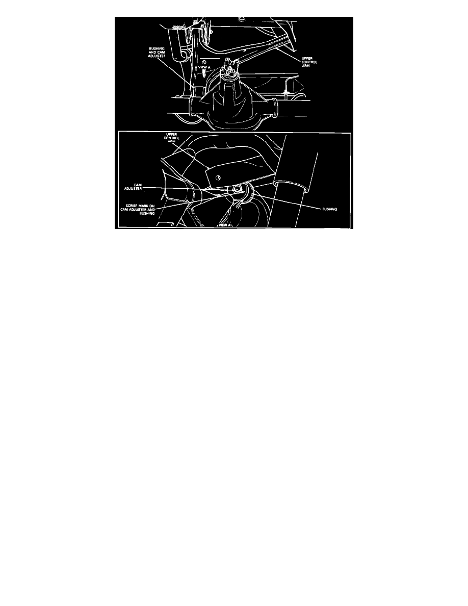
Fig. 1 Aligning Scribe Marks On Cam Adjuster And Bushing
1.
Raise and support rear of vehicle.
2.
Using a suitable jack to support rear axle, disconnect shock absorber from lower mounting, then lower axle assembly until all spring pressure is
relieved.
3.
Remove control arm to rear axle retaining nuts and bolts. Scribe alignment mark on cam adjuster and axle bushing, then disconnect upper control
arms from axle assembly.
4.
Remove control arm to right frame bracket retaining nut and bolt, Fig. 10, then rotate arm and disengage from bracket.
5.
Remove control arm to left frame bracket retaining nut, washer, outer insulator and spacer.
6.
Disengage control arm from left frame bracket, then remove inner insulator, washer and control arm.
7.
Reverse procedure to install, noting the following:
a. When installing upper control arm, ensure scribe marks on cam adjuster and bushing are properly aligned as shown in Fig. 1. Do not tighten
retaining nuts and bolts until springs have been installed and axle is at normal ride position.
b. When installing coil springs, ensure tapered coil (white marking) of spring faces upward.
c. Tighten control arm to left frame bracket retaining nut to specifications, control arm to right frame bracket retaining nut and bolt to
specifications, control arm to rear axle retaining nut and bolt to specifications and shock absorber lower mounting bolt and nut to
specifications.