
Aerostar AWD V6-183 3.0L (1991)
Ball Joint: Service and Repair
Ball Joint, Lower
Fig. 2 Knuckle Assembly Removal
1.
Place steering wheel and steering system in ``on center'' position.
2.
Remove wheel cover and hub nut.
3.
Raise and support vehicle on a twin post hoist with safety stands under the frame. The front hoist post is used to keep the spring under
compression. Ensure vehicle is securely supported on safety stands.
4.
Remove wheel and tire assembly.
5.
Remove caliper and rotor from steering knuckle.
6.
Remove cotter pin and nut from tie rod end stud, then the slotted nut.
7.
Disconnect tie rod from knuckle using puller, tool No. T64P-3590-F or equivalent.
8.
Ensure hoist is supporting lower control arm, then remove cotter pin and loosen nut retaining knuckle to lower control arm ball joint.
9.
Using puller tool No. T64P-3590-F or equivalent, disconnect lower ball joint and remove ball joint retaining nut.
10.
With vehicle supported on safety stands, pull down on knuckle until lower ball joint is disengaged from steering knuckle. Ensure vehicle is
securely supported on safety stands.
11.
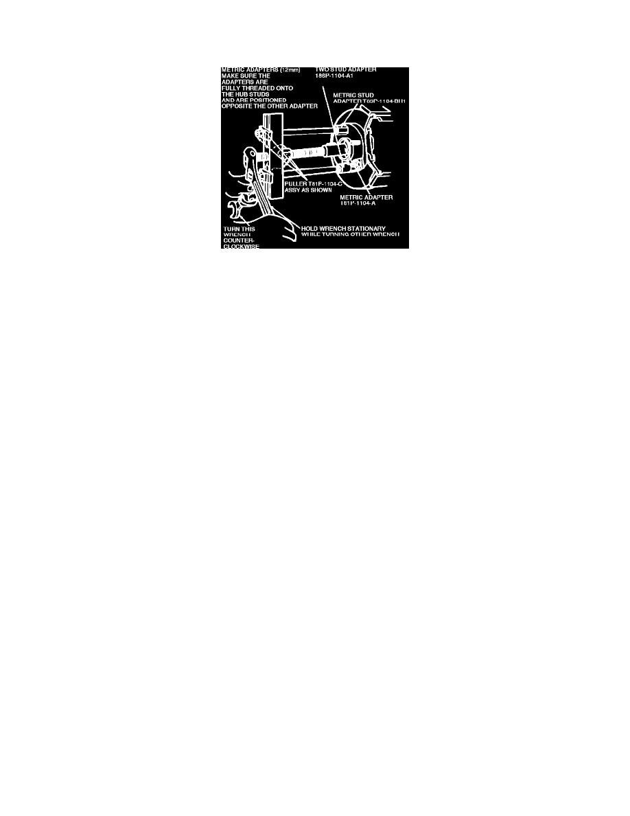
Install hub remover tool No. T81P-1104-A with tool No. T81P-1104-C and adapters tool No. T83P-1104-BH1 and tool No. T88P-1104-A1 or
equivalent. Free hub, bearing and knuckle assembly from halfshaft by pushing in CV joint outer shaft until it is loose in knuckle assembly, Fig. 2.
12.
Remove bolt and nut retaining spindle to upper control arm ball joint. While supporting halfshaft, remove knuckle by pulling downward and out of
upper ball joint from halfshaft.
13.
Reverse procedure to install, noting the following:
a. Install lower ball joint first and tighten ball joint studs to specifications.
b. Torque upper ball joints studs and hub nut to specifications.