
Aerostar AWD V6-183 3.0L (1991)
Differential Case: Adjustments
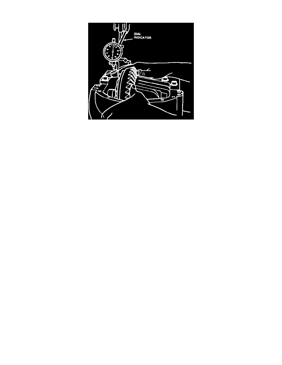
Fig. 4 Total Differential Case Endplay Check
1.
Attach ring gear to differential case using new bolts, then torque bolts alternately and evenly to specifications.
2.
Clean trunnions on differential and install bearings onto differential case. Remove all burrs and nicks from hubs so bearings rotate freely.
3.
Place differential case into carrier (without pinion). Differential case should move freely in carrier assembly. Position a suitable dial indicator
against differential case flanges. Locate tip of indicator on flat surface of one ring gear bolt, Fig. 4. Force differential case toward dial indicator as
far as possible and zero dial indicator with force still applied. Dial indicator should have a minimum of .200 inch travel on models except 35-IFS
or .350 inch on model 35-IFS. Force differential case away from dial indicator as far as it will go. Repeat this procedure until same reading is
obtained. Record dial indicator reading as measurement ``A'' on a worksheet for calculating ring gear backlash and differential bearing preload
shims. This reading indicates amount of shims needed behind differential side bearings to take up total clearance between differential bearing cup
and carrier. This reading will be used during ``Pinion & Ring Gear Backlash'' described under ``Carrier Assembly.''
4.
Remove differential case from carrier. Do not remove differential case bearings at this time.