
Aerostar AWD V6-183 3.0L (1991)
Pinion Gear: Adjustments
Backlash
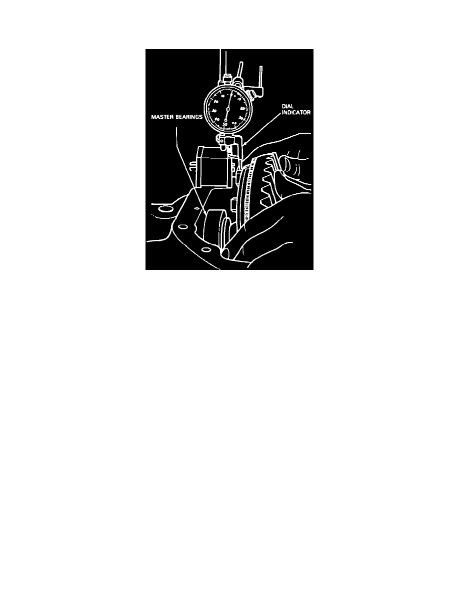
Fig. 7 Total Differential Case Endplay Check
1.
Place differential case into position in carrier (differential case bearings should still be installed).
2.
Force differential case away from drive pinion gear, until it is completely seated against cross bore face of carrier. Position a dial indicator so
indicator tip rests on a ring gear bolt head, Fig. 7. Zero dial indicator.
3.
Force ring gear against pinion gear. Rock ring gear slightly to ensure gear teeth are in contact, then force ring gear away from pinion gear,
ensuring dial indicator returns to zero. Repeat this procedure until dial indicator reading is the same. This reading should be recorded as
measurement ``B'' and reveals amount of shims necessary between differential case and differential bearing on ring gear side.
4.
Assemble shim pack for ring gear side to measurement ``B.''
5.
Subtract measurement ``B'' from measurement ``A'' obtained in step 3 under ``Total Differential Case Endplay'' as previously described to obtain
measurement ``C.'' Measurement ``C'' equals amount of shims required between differential case and bearing on side opposite of ring gear.
6.
Assemble shim pack for side opposite of ring gear to measurement ``C'' plus (+) .015 inch.
7.
Remove differential case from carrier, then the bearings from case.
8.
Place required amount of shims on hub of ring gear side of differential case, then install bearing and drive bearing onto hub using a suitable
differential side bearing replacer.
9.
Place required amount of shims on hub of differential case opposite of ring gear side, then install bearing. Place a suitable step plate on ring gear
side bearing to protect bearing, then drive bearing opposite of ring gear side onto hub using differential side bearing replacer.
10.
Install differential bearing cups onto bearings.
11.
Mount Spreader tool No. TOOL-4000-E and Spreader Adapter tool No. T80T-4000-B or their equivalents onto carrier assembly.
12.
Position a dial indicator onto carrier, then spread housing. Do not spread housing more than .015 inch.
13.
Install differential case into carrier. If necessary, use a rawhide or plastic hammer to seat case in carrier bore. With partial and
non-hunting/partial ring gear and pinion sets, align marks on ring gear and drive pinion, if applicable. Use care not to nick teeth of ring
gear or pinion.
14.
Remove spreader and dial indicator.
15.
Install bearing caps and bolts, ensuring letters or numbers stamped on caps correspond in both position and direction with letters or numbers
stamped into carrier, then torque bolts to specifications.