ford Workshop Repair Guides

Ford Workshop Service and Repair Manuals

Anti-lock Brake (ABS) Control Module <--> [Electronic Brake Control Module]|Locations|Page 2811 > < Anti-lock Brake (ABS) Control Module <--> [Electronic Brake Control Module]|Locations
Page 1
background image

Anti-lock Brake (ABS) Control Module: Diagrams
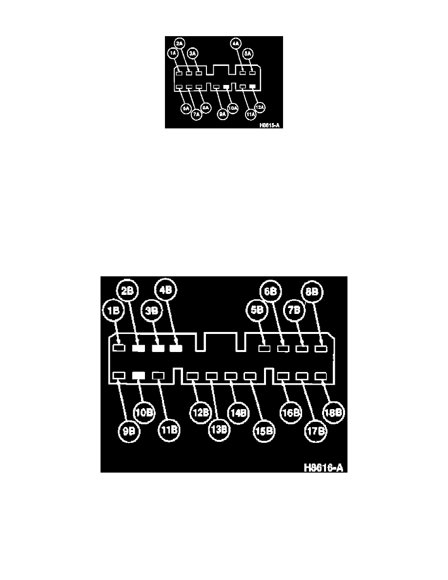
Connector

Pin    

Circuit    

Circuit Function 

1A        

402 (BK/Y)        

Right Rear Solenoid

2A        

404 (BL/O)        

Right Front Solenoid

3A        

51 (BK)        

Module Ground

4A        

407A (Y/W)        

Solenoid Monitor

5A        

351F (GN)        

Brake ON/OFF Switch Input

6A        

403 (Y/GN)        

Left Front Solenoid

7A        

401 (BR)        

Left Rear Solenoid

8A        

51A (BK)        

Module Ground

9A        

60A (BK/W)        

Module Power

10A        

--            

NOT USED

11A        

405C (R/Y)        

Motor Monitor

12A        

--            

NOT USED

Connector

Pin    

Circuit    

Circuit Function 

1B        

409 (GN/BK)    

Data Link Connector

2B        

--            

NOT USED

3B        

--            

NOT USED

4B        

--            

NOT USED

5B        

412 (Y)        

Right Front Brake Anti-Lock Sensor

Anti-lock Brake (ABS) Control Module <--> [Electronic Brake Control Module]|Locations|Page 2811 > < Anti-lock Brake (ABS) Control Module <--> [Electronic Brake Control Module]|Locations