
Aspire L4-81 1.3L SOHC (1994)
Throttle Position (TP) Sensor: Adjustments
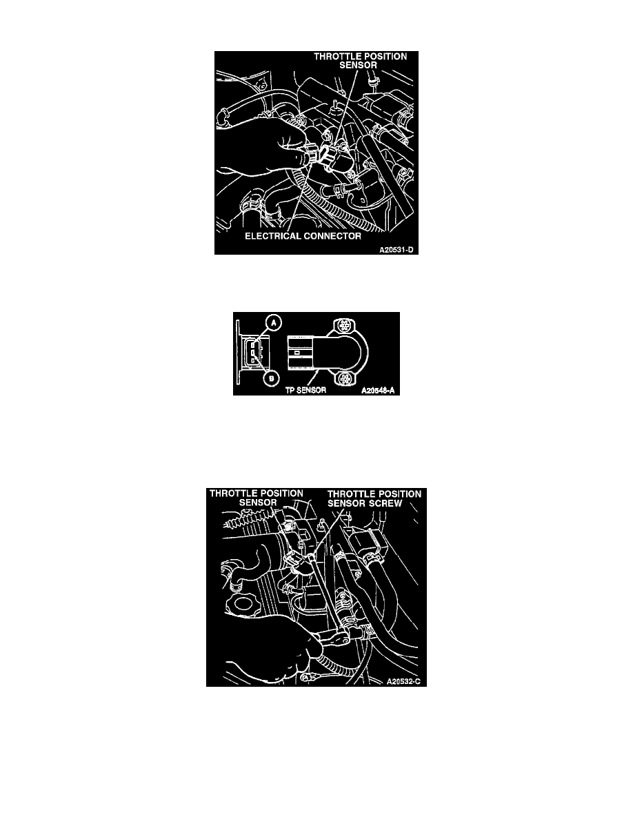
Throttle Position Sensor
1. Disconnect the Throttle Position (TP) sensor electrical connector.
Throttle Position Sensor
2. Connect Rotunda 73 Digital Multimeter 1O5-OOO51, or equivalent, between terminals A and B of the sensor.
3. Turn the throttle lever to the Wide Open Throttle (WOT) position and check the resistance reading on the multimeter.
The reading should be approximately 5K ohms.
4. Turn the throttle lever to the fully closed position and check the reading on the multimeter. The reading should be below 1 ohm.
Throttle Position Sensor
5. If the resistances are not within the specifications, adjust the TP sensor as follows:
a. Loosen, but do not remove, the TP sensor screws.
b. With the throttle lever in the closed position, adjust the TP sensor until the multimeter reads below 1 ohm.
c. Turn the throttle lever to the WOT position and check the resistance. The resistance should be approximately 5K ohms. If the TP sensor
cannot be adjusted to specification, the throttle body must be replaced.
d. After the TP sensor resistance readings are to specification, tighten the TP sensor screws to 1.6-2.3 Nm (14.2-20.3 lb in).