
Aspire L4-81 1.3L SOHC (1994)
soft jaw vise.
d. Tighten center bolt in increments to 36, 72, 108, and 145 ft lb. After bolt is tightened to each specification, remove assembly from vise and
rotate steering knuckle to seat bearings.
e. Again clamp steering knuckle in vise, then measure the amount of torque necessary to start rotation of center bolt using an inch pound torque
wrench.
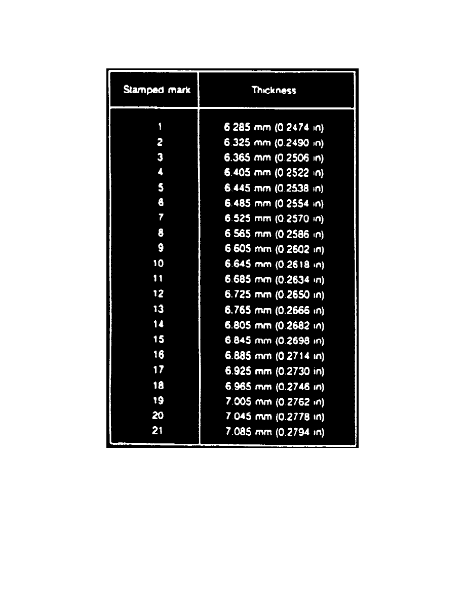
Fig. 6 Bearing Preload Spacer Identification Chart
f.
If torque reading is 2.2-10.4 in lb, spacer is correct thickness. If torque reading is less than 2.2 in lb, a thinner spacer must be used. If torque
reading is greater than 10.4 in lb, a thicker spacer must be used. Twenty one spacers of various thicknesses are available for service. Each
spacer has a number stamped on it for identification purposes, Fig. 6. Changing the spacer by one number, either up or down, will result in a
1.7-3.5 in lb change in bearing preload.
15. Pack bearings and hub with suitable high temperature grease, then install inner bearing into steering knuckle.
16. Lubricate seal lip, then install new inner seal using suitable tool.
17. Place original bearing preload spacer, or spacer selected in step 14, into steering knuckle.
18. Lubricate seal lip, then install outer wheel bearing and new outer seal into knuckle.
19. Position rotor onto hub, aligning marks made during disassembling, then1install attaching bolts.
20. Place hub/rotor assembly into steering knuckle bore, then press assembly fully into knuckle using suitable tools.
21. Follow steps 1 through 7 in reverse order to complete installation and note the following:
a. Apply a thin coat of grease to halfshaft splines before installing steering knuckle and hub/rotor assembly.