
Bronco Full Size L6-300 4.9L (1987)
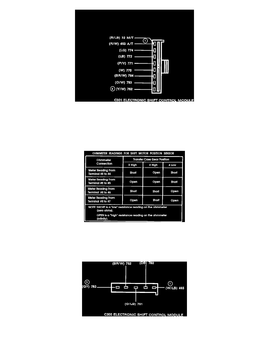
Eight-wire Pigtail Harness Connector (Electronic Shift) C301
1.
Connect an ohmmeter between terminal one and ground, if vehicle is equipped with a Manual Transmission (M/T), DEPRESS clutch pedal.
Ohmmeter should indicate less than 50 ohms resistance. If vehicle is equipped with an Automatic Transmission (A/T), shift transmission into
NEUTRAL. Ohmmeter should indicate less than 50 ohms resistance.
2.
Connect an ohmmeter between terminals two and three.This will check continuity of speed sensor that is located in the transfer case. The speed
sensor picks up rotating speed of the output shaft from two notches that are cut in opposite sides of the outer ring of the clutch housing assembly.
Ohmmeter should indicate between 200 and 350 ohms.
Checking Ohmmeter Reading For Shift Motor Position Sensor (Electronic Shift)
3.
Connect an ohmmeter between terminal eight and terminals four, five, six and seven respectively. Refer to chart for appropriate ohmmeter
readings in each transfer case position.
FIVE-WIRE PIGTAIL HARNESS CONNECTOR
Fig. 7 Five-wire Pigtail Harness Connector (Electronic Shift) C300
1.
Connect an ohmmeter between terminals one and two, then DEPRESS 4x4 (2H-4H) switch. Ohmmeter should indicate less than 50 ohms of