
Bronco Full Size L6-300 4.9L (1987)
Electronic Shift Control Module: Testing and Inspection
Control Module Circuits
Main Feed Connector
There are three wiring harnesses connected to the electronic control module:
^
The eight-wire pigtail harness connector
^
The five-wire harness connector
^
The eight-wire harness connector
To check the integrity of these circuits, disconnect harnesses from the electronic control module and perform the following checks:
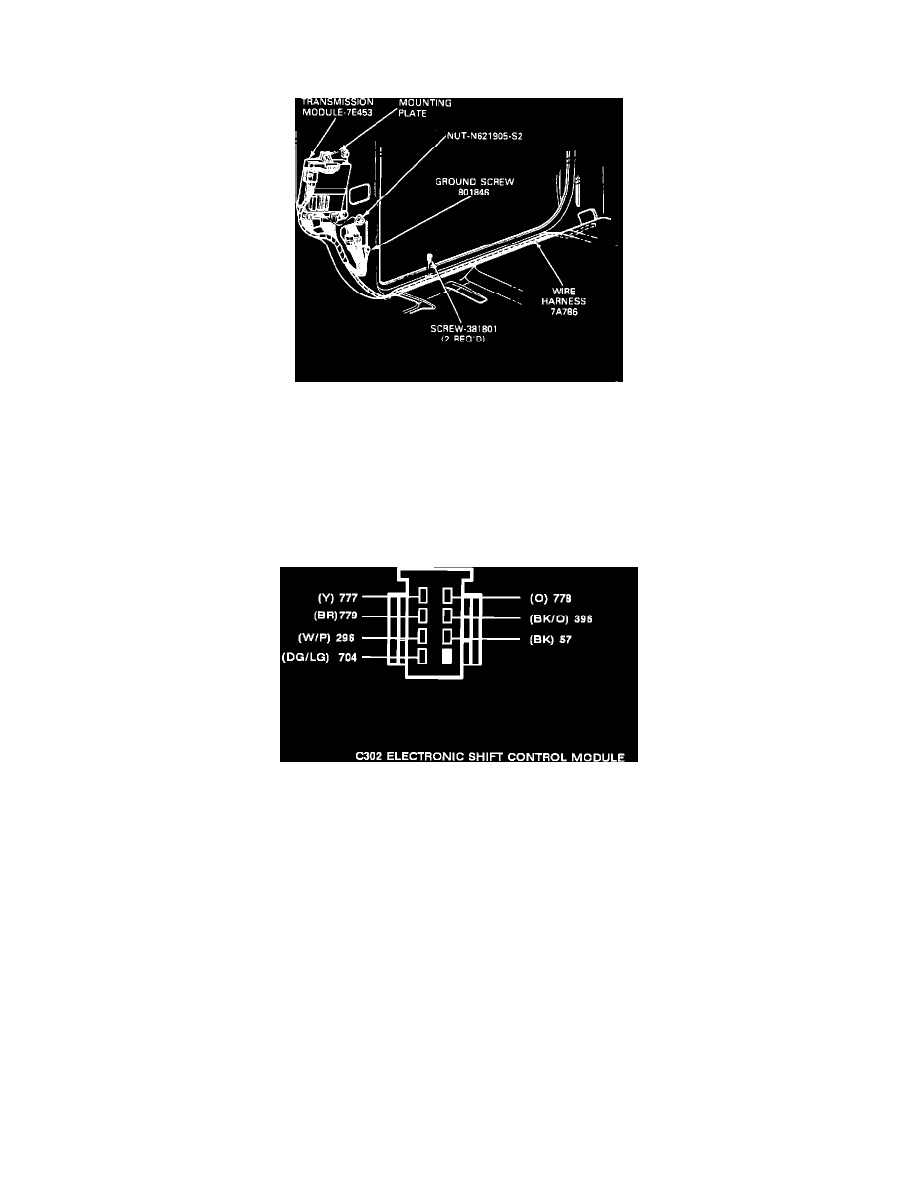
EIGHT-WIRE PIGTAIL HARNESS CONNECTOR
Eight-wire Pigtail Harness Connector (Electronic Shift) C302
1.
Connect a voltmeter between terminal eight and ground. Voltmeter should indicate battery voltage.
2.
Connect a voltmeter between terminal seven and ground, then turn ignition switch to Run position. Voltmeter should indicate battery voltage.
3.
Connect an ohmmeter between terminal 6 and ground. Ohmmeter should indicate less than ten ohms resistance.
4.
Connect an ohmmeter between terminals four and five. Ohmmeter should indicate less than ten ohms resistance.
5.
Connect an ohmmeter between terminal three and ground. Ohmmeter should indicate zero ohms.
6.
Connect an ohmmeter between terminal two and ground. Ohmmeter should indicate zero ohms.
EIGHT-WIRE HARNESS CONNECTOR