
Bronco Full Size L6-300 4.9L (1987)
Electronic Shift Control Module: Testing and Inspection
Control Module Self Test, Borg-Warner 13-56
The electronic control module has a diagnostic capability of its internal circuitry. Self test procedure is as follows:
1.
Disconnect five-wire and eight wire connectors from electronic control module.
2.
Turn ignition switch to the RUN position.
3.
Activate the self test switch and note result:
Control Module Self Test
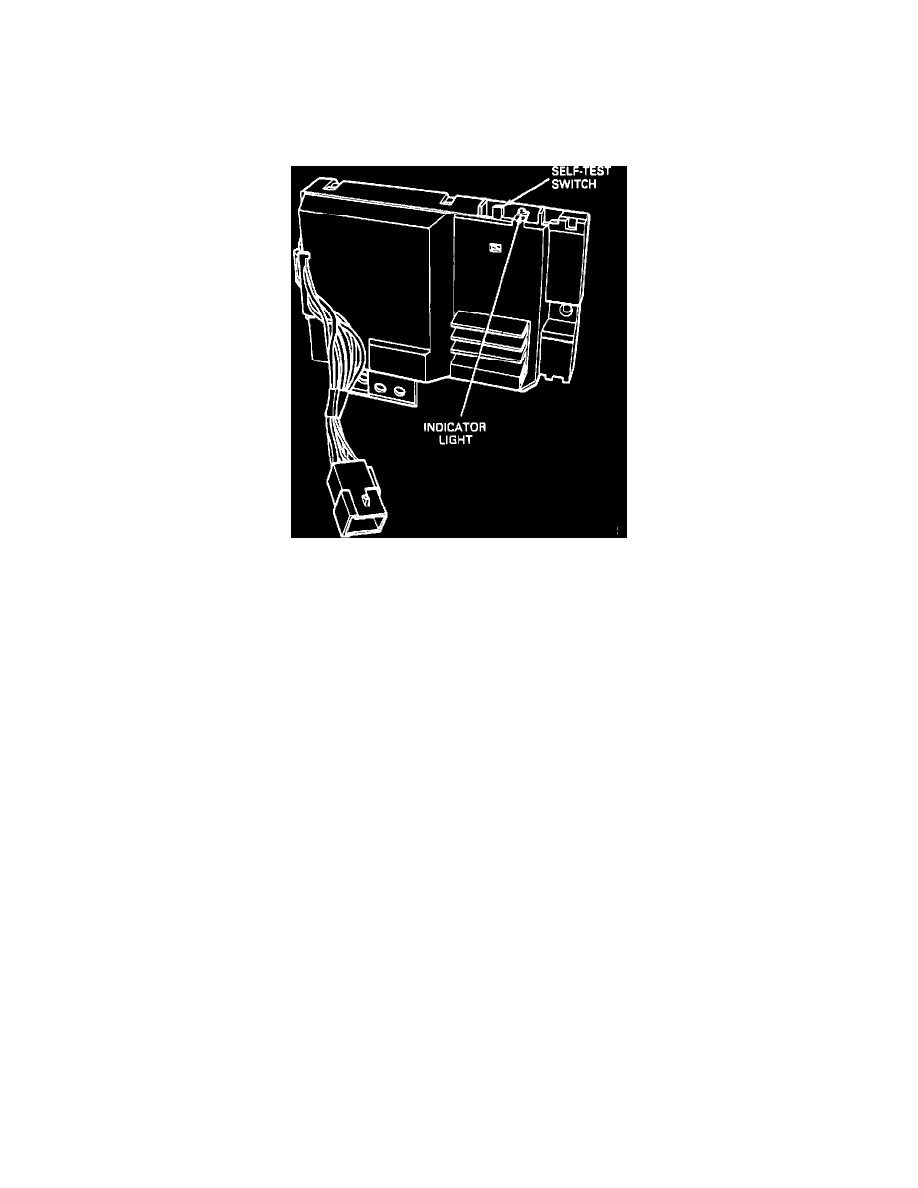
NOTE: The self test switch and indicator light is located on the Electronic Control Module.
A FLASHING INDICATOR LAMP, (approximately one flash per second), indicates control module is functioning properly.
A STEADY INDICATOR LIGHT, indicates that control module is inoperative and must be replaced.