
Bronco Full Size V8-302 5.0L (1986)
Intake Manifold: Service and Repair
Removal and Installation
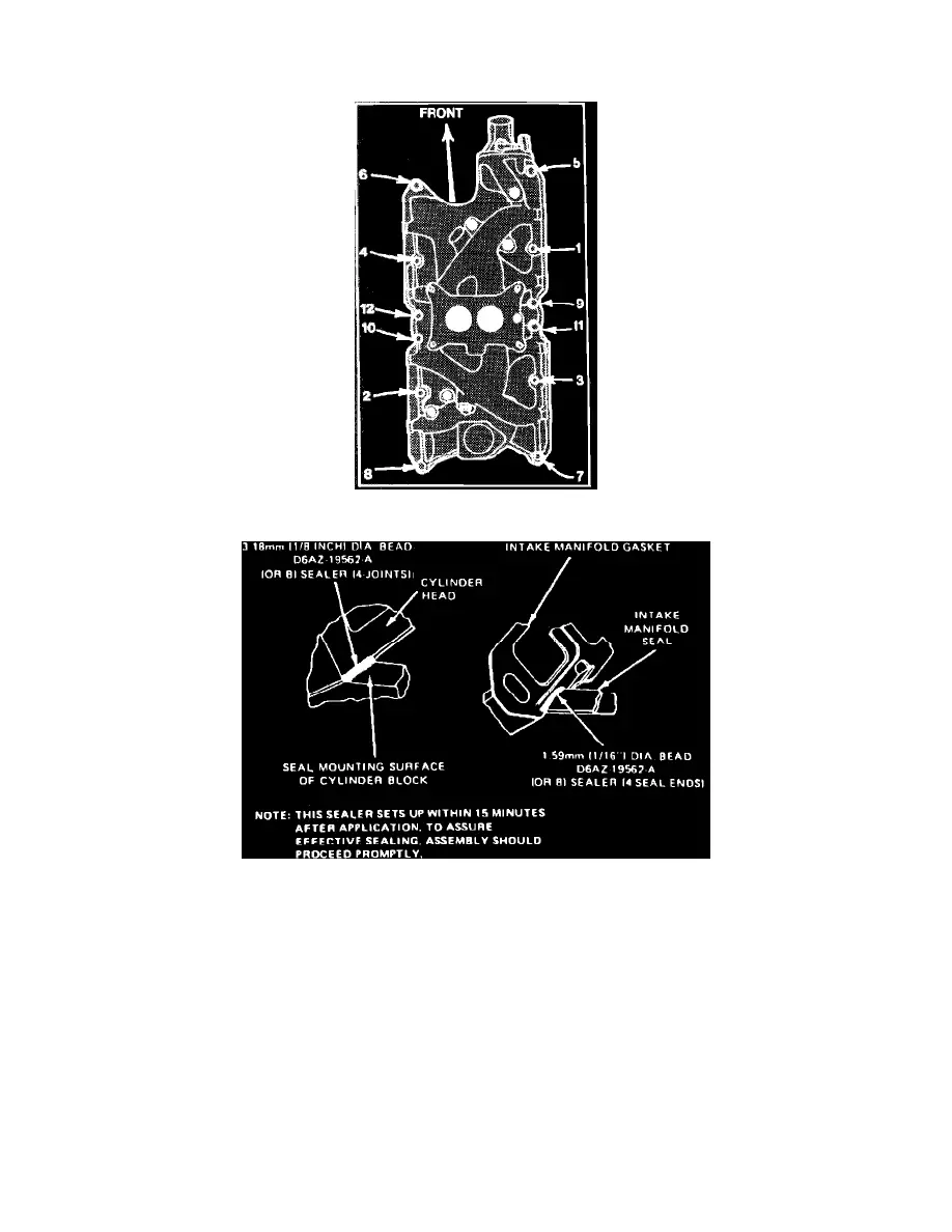
Fig. 13 Intake manifold tightening sequence. V8-255, 302 & V8-351W
Fig. 20 Intake manifold installation. V8 engines
V8-255, 302 & 351W
1.
Drain cooling system, then remove air cleaner with intake duct assembly and crankcase ventilation hose.
2.
Disconnect accelerator cable and speed control linkage (if equipped) from carburetor or throttle body. Remove accelerator cable bracket, then
disconnect kickdown rod from carburetor or throttle body on models equipped with automatic transmission. Disconnect electric choke, carburetor
solenoid electrical connectors or EEC connector, if equipped.
3.
Disconnect high tension lead and wires from ignition coil.
4.
Disconnect ignition wires from spark plugs, then remove wires and bracket assembly from rocker arm cover attaching stud.
5.
Remove distributor cap and ignition wires as an assembly.
6.
Disconnect fuel inlet line from carburetor or throttle body.
7.
Disconnect vacuum hoses from distributor, then remove distributor and disconnect evaporative hoses, if equipped.
8.
Disconnect upper radiator hose from coolant outlet housing.
9.
Disconnect electrical connector from coolant temperature sending unit, then remove heater hose from intake manifold.
10.
Remove water pump bypass hose from coolant outlet housing, then disconnect crankcase vent hose from rocker arm cover.
11.
Remove intake manifold attaching bolts, then the intake manifold, carburetor or throttle body as an assembly.
12.
Reverse procedure to install. Apply sealer as shown in Fig. 20. Torque manifold attaching bolts to 23-25 ft-lbs in sequence as shown in Fig. 13.