
Bronco II 4WD V6-171 2.8L (1985)
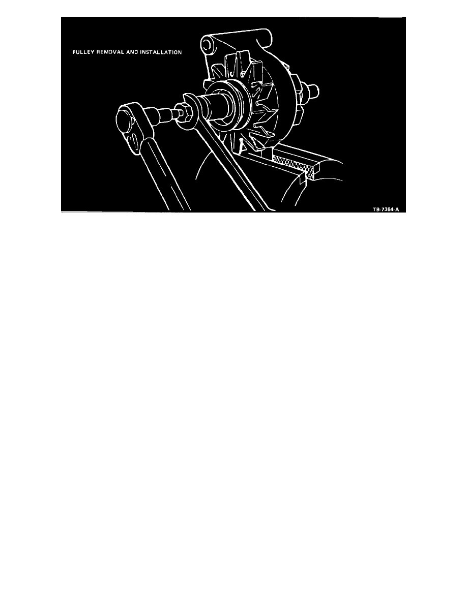
Figure 11
9.
Clamp the front housing in a vise with protective jaws (Figure 11).
10.
Remove the drive pulley retaining nut from the rotor using removal and installation tool, T65P- 10300-B or equivalent
(Figure 11).
11.
Remove the flat washer, drive pulley, fan and fan spacer from the rotor shaft.
12.
Remove the rotor from the housing and remove the housing from the vise.
13.
Remove the front rotor stop from the rotor shaft. Do not remove the stop ring from the rotor shaft unless it is damaged.
14.
Remove the screws attaching the bearing retainer to the front housing and remove the retainer.
15.
Remove the bearing from the front housing. If the bearing will not slide out, remove it using a suitable arbor press.
Support the bearing close to the bearing boss to prevent damage to the housing.
Cleaning and Inspection
CAUTION: WHEN REBUILDING AN INTEGRAL ALTERNATOR, USE ONLY HIGH TEMPERATURE BEARINGS. USE OF STANDARD
PARTS WILL RESULT IN ALTERNATOR FAILURE.
1.
Wipe the stator, rotor and front bearing with a clean cloth. Do not clean these parts with solvent.
2.
Rotate the front bearing on the drive end of the rotor shaft. Check for any scraping noise, looseness or roughness. Look for excessive lubricant
leakage. If any of these conditions exist, replace the bearing.
3.
Inspect the rotor shaft rear bearing surface for roughness or severe chatter marks. Replace the rotor assembly if the shaft is not smooth.
4.
Place the rear bearing on the slip ring end of the rotor shaft and rotate the bearing. Make the same check for noise, looseness and roughness as was
made for the front bearing. Inspect the rollers and cage for damage. Replace the rear bearing if these conditions exist or if the lubricant is lost or
contaminated.
5.
Check the slip rings for nicks and scratches. These may be removed by turning down the slip rings. Do not go beyond a minimum diameter of 31
mm (1.22 inches). If the rings are badly damaged, replace the rotor assembly.
6.
Check all wire leads on both the rotor and stator assemblies for loose or broken connections. Check the windings for burned insulation. Replace
parts that show signs of burned insulation.
7.
Check the pulley and fan for excessive looseness on the rotor shaft and for cracks or other damage. Replace any pulley or fan that is loose, cracked
or bent out of shape.
8.
Check both the front and rear housings for cracks, particularly in the webbed areas at the mounting ear. Replace a damaged or cracked housing.