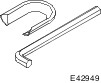
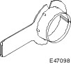
| Removal and Installation Special Tool(s) | | Remover, Halfshaft 204-226 (16-092) | | | Adapter for 204-226 204-226-01 (16-092-01) | | | Protector, Ball Joint Gaiter 204-349 | | | Slide Hammer 205-047 (15-011) | | | Protector, Halfshaft Seal 205-775 | | | Remover, Halfshaft 308-256 (16-089) | General Equipment Ball joint separator Tire lever Materials Name Specification Silicone Grease ESE-M1C171-A Transmission Fluid WSD-M2C200-C Removal All vehicles | | -
Remove the wheel and tire.
For additional information, refer to: Wheel and Tire (204-04 Wheels and Tires, Removal and Installation).
| | | -
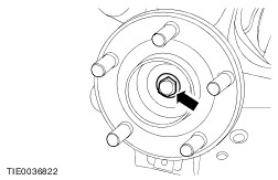
Remove the wheel hub retaining bolt. - Discard the wheel hub retaining bolt.
| | | -
NOTE:Use a suitable brass drift if necessary. Push the halfshaft into the tripode housing as far as the stop (approximately 20 mm). | | | -
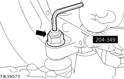
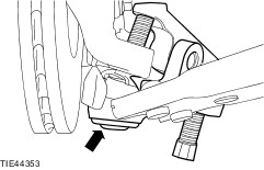
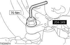
Using the special tool to prevent the ball joint stud from rotating, remove and discard the lower arm ball joint retaining nut. | | | -
CAUTION:Make sure the special tool is installed with the curved surface facing upwards to prevent damage to the ball joint seal. Install the special tool. | | | -
CAUTION:Make sure the strut and spring assembly does not move in a forwards or rearwards direction, to prevent damage to the top mount center cup. | | | -
CAUTION:The inner constant velocity (CV) joint must not be bent more than 23 degrees. The outer CV joint must not be bent more than 45 degrees. CAUTION:Do not apply excessive force to the strut and spring assembly. Do not pull the strut and spring assembly outwards by more than 28 mm. CAUTION:Make sure the strut and spring assembly does not move in a forwards or rearwards direction, to prevent damage to the top mount center cup. NOTE:Make sure the halfshaft is still fully engaged in the tripode housing. Detach the halfshaft from the wheel hub. - Pull the strut and spring assembly outwards approximately 28 mm.
| Vehicles with 5-speed manual transaxle (iB5) | | -
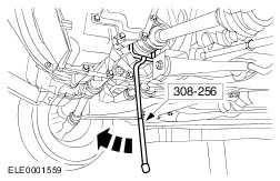
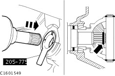
CAUTION:The inner CV joint must not be bent more than 23 degrees. The outer CV joint must not be bent more than 45 degrees. CAUTION:Make sure the halfshaft seal is not damaged. NOTE:Plug the transaxle to prevent oil loss or dirt ingress. Using the special tool, remove the halfshaft. - Allow the oil to drain into a suitable container.
| Vehicles with 4-speed automatic transaxle | | -
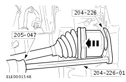
CAUTION:The inner CV joint must not be bent more than 23 degrees. The outer CV joint must not be bent more than 45 degrees. CAUTION:Make sure that the halfshaft seal is not damaged. CAUTION:Plug the transaxle to prevent oil loss or dirt ingress. Using the special tools, remove the halfshaft. - Allow the oil to drain into a suitable container.
| Vehicles with 5-speed manual transaxle (MTX75) or 6-speed manual transaxle (MMT6) | | -
CAUTION:The inner CV joint must not be bent more than 23 degrees. The outer CV joint must not be bent more than 45 degrees. CAUTION:Make sure that the halfshaft seal is not damaged. CAUTION:Plug the transaxle to prevent oil loss or dirt ingress. Using the special tools, remove the halfshaft. - Allow the oil to drain into a suitable container.
| Vehicles with automatic transaxle (CFT23) | | -
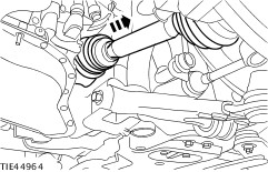
CAUTION:The inner CV joint must not be bent more than 23 degrees. The outer CV joint must not be bent more than 45 degrees. CAUTION:Make sure that the halfshaft seal is not damaged. CAUTION:Plug the transaxle to prevent dirt ingress. Using a suitable tire lever, remove the halfshaft. | Installation Vehicles with automatic transaxle (CFT23) | | -
Coat the halfshaft seal with grease. | All vehicles | | -
CAUTION:The inner CV joint must not be bent more than 23 degrees. The outer CV joint must not be bent more than 45 degrees. CAUTION:Make sure that the halfshaft seal is not damaged. CAUTION:Make sure the snap ring is correctly seated. NOTE:Install a new snap ring. Attach the left-hand halfshaft to the transaxle. - Remove the special tool before fully installing the halfshaft.
| | | -
Push the halfshaft into the tripode housing as far as the stop (approximately 20 mm). | | | -
CAUTION:The inner CV joint must not be bent more than 23 degrees. The outer CV joint must not be bent more than 45 degrees. CAUTION:Do not apply excessive force to the strut and spring assembly. Do not pull the strut and spring assembly outwards by more than 28 mm. CAUTION:Make sure the strut and spring assembly does not move in a forwards or rearwards direction, to prevent damage to the top mount center cup. Attach the halfshaft to the wheel hub. - Pull the strut and spring assembly outwards approximately 28 mm.
| | | -
CAUTION:Make sure the strut and spring assembly does not move in a forwards or rearwards direction, to prevent damage to the top mount center cup. Attach the lower arm ball joint to the wheel knuckle. | | | -
WARNING:Install a new lower arm ball joint retaining nut. Failure to follow this instruction may result in personal injury. Using the special tool to prevent the ball joint from rotating, install the lower arm ball joint retaining nut. | | | -
CAUTION:Install a new wheel hub retaining bolt. NOTE:Do not tighten the wheel hub retaining bolt at this stage. Install the wheel hub retaining bolt. | | | -
Install the wheel and tire.
For additional information, refer to: Wheel and Tire (204-04 Wheels and Tires, Removal and Installation).
| | | -
Tighten the wheel hub retaining bolt (wheel and tire shown removed for clarity). - Tighten the wheel hub retaining bolt in two stages.
| Vehicles with 4-speed automatic transaxle | | -
With the vehicle on a level surface, check the transmission fluid level.
For additional information, refer to: Transmission Fluid Drain and Refill (307-01B Automatic Transmission/Transaxle - Vehicles With: 4-Speed Automatic Transmission (4F27E), General Procedures).
| Vehicles with manual transaxle | | -
With the vehicle on a level surface, check the transmission fluid level and top up with clean transmission fluid until the fluid level is 5 - 10 mm below the fluid filler plug. | |