| Diagnosis and Testing Worldwide Diagnostic System (WDS) Principles of Operation (Vehicles with Central Locking) Central locking system overview This system consists of mechanical/electrical operated latches. The latch motors are interlinked by solid wiring. Central locking is achieved with mechanical switching in the door latch by key or remote handle. When a key is rotated in the door lock cylinder or an interior remote handle is operated, switching contacts within the door latch supply ground signals to the central junction box (CJB) electronic control, which in turn controls central locking relays. The relays supply battery voltage and ground to the door latch motors. By reversing the battery voltage and ground connections at the central locking relays, the door latches can be locked or unlocked. The liftgate or luggage compartment lid is opened when the vehicle is in the unlocked mode by a ground signal from the liftgate/luggage compartment lid release switch to the CJB control. The CJB will then supply a voltage to the liftgate/luggage compartment lid latch motor. If the vehicle is locked, the input from the liftgate/luggage compartment lid release switch to the CJB will be ignored. Principles of Operation (Vehicles with Remote Keyless Entry (RKE) RKE locking system overview This system consists of mechanical/electrical operated door latches driven by inputs from electronic door control modules. The system uses a radio frequency (RF) transmitter and receiver to operate the remote lock/unlock functions and normal key or remote door handle inputs for standard central and double locking functions. When a key is rotated in the door lock cylinder or an interior remote handle is operated, switching contacts within the door latch supply a command signal to the door control module. The door control module communicates with the CJB using the central area network (CAN) bus circuit. Dependant upon the current state of the locking system, commands are then sent to all of the door control modules, which in turn allow battery voltage to be applied to the door latch motors. The fuel filler door lock function is controlled by the CJB. The CJB receives the lock command from the door control module. The CJB operates the lock relay which supplies a voltage to the fuel filler door lock motor. To unlock the fuel filler door, the supplied voltage is reversed using the driver door/fuel filler door unlock relay. The liftgate or luggage compartment lid is opened when the vehicle is in the unlocked mode by a ground signal from the liftgate/luggage compartment lid release switch to the CJB. The CJB will supply a voltage to the liftgate or luggage compartment lid latch motor. If the vehicle is locked, the input from the liftgate/luggage compartment lid release switch will be ignored. The RKE functions are operated by sending a radio frequency (RF) signal from the key transmitter. The signal is received by the vehicle remote RF receiver. The signal received is transferred as a data signal to the CJB, where the transmitted signal is validated and control commands are sent to the door control modules on the CAN bus circuit and to the liftgate/luggage compartment lid latch motor by direct wiring. Inspection and Verification (Vehicles with Remote Keyless Entry (RKE) - Verify the customer concern.
- Visually inspect for obvious signs of mechanical or electrical damage.
Visual Inspection Chart | Mechanical | Electrical | - Misaligned door(s), hood, liftgate, tailgate, luggage compartment and hood
- Door latch(es)
- Liftgate latch
- Luggage compartment lid latch
- Hood latch
- Actuating Cable(s)
- Exterior door handle(s)
- Door latch remote control(s)
- Door lock cylinder(s)
- Liftgate lock cylinder
| - Fuse(s)
- Relay(s)
- Wiring harness
- Electrical connector(s)
- Door latch(s)
- Remote transmitter batteries
- Vehicle battery
- Remote transmitter
- RF receiver
- Liftgate exterior release switch
- Luggage compartment lid release switch
- Door control module(s)
- CJB
| - If an obvious cause for an observed or reported concern is found, correct the cause (if possible) before proceeding to the next step.
- If the cause is not visually evident, connect WDS to the data link connector.
- Select the Generic Electronic Module menu.
- Retrieve the diagnostic trouble codes (DTCs) and refer to the Diagnostic Trouble Code (DTC) Index - CJB.
Principles of Operation (Vehicles with Keyless vehicle system) Keyless Component Installation, Programing and Initialization If new components for the keyless vehicle system have been installed, dependant upon which component is installed, programing using WDS will be required. NOTE:Before any programing or initialization for the keyless vehicle system components can be carried out, an operational valid passive anti-theft system (PATS) emergency key must be present in the ignition switch turning knob. Passive Key programing Passive key programing can only be carried out using WDS. To program a new passive key, clear passive keys or count passive keys follow the WDS menu sequence: - Vehicle communication
- Toolbox
- Body
- Security
- Remote Keyless Entry
From the Remote Keyless Entry screen you can choose to: - Add Keys
- Clear Keys
- Count Keys
Steering column lock control unit initialization If a new steering column lock control unit is installed, the only procedure required providing the original steering lock barrel has been installed and the original emergency key is used, is Initialize System using the following WDS menu sequence: - Vehicle communication
- Toolbox
- Body
- Security
- Remote Keyless Entry
- Initialize System
Keyless vehicle module programing If a new keyless vehicle module is installed, the following programing sequence must be followed using WDS. - Keyless Vehicle Module (KVM) programing. (From the module programing menu)
- Initialize System
Instrument cluster programing If a new instrument cluster is installed, the following programing sequence must be followed using WDS. - Instrument cluster module programing. (From the module programing menu).
- PATS key learning. (From the PATS menu)
- Initialize with the powertrain control module. (From the PATS menu)
- Initialize with the keyless vehicle module. (From the Remote Keyless Entry menu)
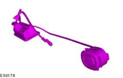
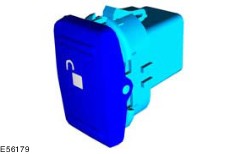
Keyless Vehicle System Overview The keyless vehicle system also incorporates RKE functions, however the main purpose of the system is to allow the operator of the vehicle to gain access to and operate the vehicle without carrying out any actions with a key or remote buttons. The keyless vehicle system can be turned off to give basic key operation if required. To isolate the keyless vehicle system, the emergency key must be inserted into the ignition switch turning knob and the ignition switch turning knob rotated to position II. It is now possible to select the KEY FREE ON or KEY FREE OFF from the instrument cluster liquid crystal display (LCD) using the remote steering column stalk control. In the OFF mode, the RKE functions still work. Vehicles equipped with keyless vehicle systems, will be delivered from production in shipping mode. Shipping mode reduces the vehicle battery drain to a minimum to extend the period of time the vehicle can remain dormant without discharging the vehicle battery. To exit the shipping mode, the emergency key must be inserted into the ignition switch turning knob and rotated to position II. The shipping mode can now be deselected from the instrument cluster LCD display using the steering column stalk control. 4 - Door exterior handle keyless vehicle antenna and lock switch 5 - Interior keyless vehicle antennas 6 - Steering column lock control unit 7 - Rear exterior keyless vehicle antenna 8 - Liftgate/luggage compartment lid lock switch Passive Key The passive vehicle key can receive an identification challenge from the vehicle door exterior handle keyless vehicle antennas within a range of approximately 1.5 meters to 2.0 meters. The challenge from the rear exterior keyless vehicle antenna will be received at up to 1.5 meters from the center rear of the vehicle. On receiving the identification challenge, the passive vehicle key will emit a coded radio frequency (RF) signal to the RF receiver. No RF signal will be emitted if the passive vehicle key does not recognize the coded low frequency challenge from the keyless vehicle module. If the system is functioning correctly, the operator will be able to open the vehicle doors, liftgate or luggage compartment lid, as long as a valid passive key is within the defined areas. If a valid passive vehicle key detects a low frequency challenge from the interior keyless antenna and emits a valid RF coded signal, the keyless vehicle module will switch on the passive go functionality. If a valid passive vehicle key is left in the vehicle and the vehicle is locked using a second valid passive vehicle key. The instrument cluster will indicate the presence of a valid key in the vehicle and the passive vehicle key left in the vehicle will be disabled. The disabled passive vehicle key can only be reactivated by starting the vehicle with the emergency key. Up to 8 passive vehicle keys can be programmed to one keyless vehicle module. Passive vehicle keys can only be programmed using the Teach Keys menu in WDS. The passive vehicle key is equipped with RKE function buttons. When an RKE function button is pressed, the RF signal emitted is received by the RF receiver within the vehicle. Data is sent from the RF receiver to the keyless vehicle module. The keyless vehicle module will validate the transmitted signal and if valid, operate the relevant function. 1 - Emergency mechanical key 3 - Ignition switch turning knob insert 4 - Ignition switch turning knob Within the passive vehicle key is concealed a emergency mechanical key. The mechanical key can be used to open the drivers door and start the vehicle. The mechanical key is equipped with a passive anti-theft system (PATS) transducer. To start the vehicle with the emergency key, it must first be assembled to the ignition switch turning knob insert. When the assembled key is inserted into the ignition switch turning knob, the key insertion detection switch sends a signal to the keyless vehicle module indicating a key has been inserted. The keyless vehicle module will then switch off the passive go and revert to standard PATS functionality. The emergency key will override the ignition lock cylinder electrical locking function. Steering Column Lock Control Unit 1 - Ignition lock cylinder release solenoid 2 - Ignition lock cylinder rotation lock 3 - Mechanical key insertion detection switch 5 - Steering column lock pin The steering column lock control unit still carries out the same function as the standard steering column lock, but now it has the added functionality of a solenoid operated ignition lock cylinder release. For the steering column lock to release in keyless vehicle mode, certain criteria must be fulfilled: - vehicles with automatic transmissions must have the brake pedal pressed
- vehicles with manual transmissions must have the clutch pedal pressed
- a valid passive vehicle key must be within the detection range of the interior keyless vehicle antenna
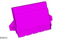
When the brake or clutch pedal is pressed, the keyless vehicle module is triggered to search for a valid passive vehicle key. If a valid passive vehicle key is detected, the ignition lock cylinder solenoid releases and the ignition switch turning knob can be pressed in. This will release the steering lock and allow the ignition switch turning knob to be rotated to positions I, II and III. To lock the steering column, the ignition switch turning knob must be turned to the 0 position and pulled out by approximately 5mm. The PATS function is armed until the ignition switch turning knob has reached position II. When the ignition switch turning knob is in position II, the keyless vehicle module receives a request from the steering column lock control unit to identify the passive key PATS transducer. The keyless vehicle module then sends a command on the medium speed CAN bus to the instrument cluster. The instrument cluster verifies the validity of the passive vehicle key PATS transducer and in turn communicates with the powertrain control module (PCM) and allows the vehicle to start. If a new steering column lock control unit is installed to a vehicle, before it will function, it must be initialized using the Initialize System menu in WDS. Liftgate/Luggage Compartment Lid Lock Button The liftgate/luggage compartment lid lock button is located in the licence plate illumination panel. If the liftgate/luggage compartment lid is closed and the exterior lock button is pressed while a valid passive vehicle key in the loadspace area, the keyless vehicle module will request that the external keyless vehicle antennas issue a passive vehicle key challenge. If no valid passive vehicle key signal is detected by the RF receiver, the liftgate/luggage compartment lid will be automatically opened. If a valid passive vehicle key signal is detected by the exterior keyless vehicle antennas, the passive vehicle key in the loadspace area will be deactivated and the vehicle allowed to lock in the normal way. The deactivated passive vehicle key will be reactivated after the ignition switch turning knob has been turned to position II with either a valid passive vehicle key or a mechanical emergency key. Interior Keyless Vehicle Antenna The interior keyless vehicle antenna function is to issue a low frequency challenge to the passive vehicle key while it is in the passenger compartment. The vehicle is equipped with two interior keyless vehicle antennas in the passenger compartment area and one in the loadspace area. The loadspace keyless vehicle antenna is fitted to prevent the possibility of accidently locking the passive vehicle key in the loadspace area. Exterior Door Handle Antenna and Lock Switch 2 - Exterior keyless vehicle antenna 3 - Exterior door lock switch With the vehicle locked and the keyless vehicle system active, the exterior keyless vehicle antennas are dormant and do not scan for a valid passive vehicle key. The exterior keyless vehicle antenna will only wake up and issue a challenge for a valid passive vehicle key when the operator has begun to pull the exterior door handle. In the time it takes to open a door, the signal determining handle movement is sent to the keyless vehicle module, a request of the exterior keyless vehicle antenna to detect a valid passive vehicle key, the receiving and validation of the passive vehicle key code and the command to the door latch to unlock has occurred. This whole process takes approximately 150 ms. The only time this function will be impaired is if the vehicle has been left standing for at least 5 days. The keyless vehicle module will then enter a state of reduced energy consumption and when the vehicle door handle is pulled, it will take a noticeably increased period for the keyless system to wake up and unlock the door(s). When the operator exits the vehicle, the vehicle is locked by pressing the lock button fitted into the exterior door handle. With all doors and liftgate/luggage compartment lid closed, the exterior door lock button will initiate a request from the keyless vehicle module to scan the interior and exterior of the vehicle around the pressed lock button for valid passive vehicle key. If a valid passive vehicle key is detected on the exterior of the vehicle only, the door latches will be locked. The door latches will remain locked for a period of 3 seconds to allow for the operator to pull the exterior door handle to check if the door is locked. After 3 seconds, if the exterior door handle is pulled, the door latch will release as in a normal keyless vehicle entry. If a valid passive vehicle key is detected in the interior of the vehicle and not on the exterior, the latches will not be locked. The vehicle will also not be locked if the ignition switch turning knob is in the II position. Passive vehicle locking will be confirmed by the operation of the vehicles turn signal lamps. If the ignition turning knob is in position I or 0 and the steering column lock is not engaged, the keyless vehicle module will allow the locking to operate. A warning chime will sound and a warning ENGAGE STEERING LOCK will be displayed in the instrument cluster LCD area if driver's door is opened. To double lock the vehicle, requires the exterior lock button to be pressed twice. The second pressing of the exterior lock button must occur within 3 seconds of it first being pressed. To operate the global closing feature, requires the exterior lock button on the drivers door only, to be pressed and held pressed for a period of 2 seconds. The keyless vehicle central unlocking function can be programed to operate the drivers door only or all the doors. To set the desired function, the lock and unlock button at the passive key has to be pressed in parallel for 4 seconds. If a rear exterior door handle or passenger exterior door handle is pulled when the keyless vehicle system is in driver door unlock mode, all doors will remain locked. If the driver exterior door handle is pulled when the keyless vehicle system is in driver door unlock mode, only the driver door will unlock and the door handle passive entry for the rear doors and passenger door will be inoperative. In driver door unlock mode, the passenger doors can only be unlocked using the interior keyless vehicle system unlock button. Exterior Door Handle Pull Switch 3 - Exterior door handle pull switch The exterior door handle switch is operated from a cam lobe attached to the door latch actuator. As the exterior door handle is pulled, the door latch actuator rotates and operates the exterior door handle pull switch. Door Latch 2 - Door latch unlatch motor 3 - Central/double locking motor The keyless vehicle locking system requires unique door latches. The door latches are equipped with electric motors that replace the mechanical unlatch function of the exterior door handle when the vehicle is in keyless vehicle system mode. This is because the exterior door handle is already in a semi pulled state before the latch unlatch command is received by the latch lock motors, the latch linkage is not in a position to engage with the exterior door handle. If the emergency key is used to enter the vehicle, the standard mechanical latch linkage is utilized. Central and double locking is still controlled by the door control modules, however the commands to lock and unlock are relayed through the keyless vehicle module on the high-speed CAN bus circuit. Interior Unlock Switch The interior unlock switches function, is to unlock the rear doors and passenger door locks when the vehicle has been entered using the passive entry system in drivers unlock mode. Keyless Vehicle Module The keyless vehicle module is at the heart of the keyless vehicle system. It communicates with the PJB and with the instrument cluster on the medium speed CAN bus circuit. The keyless vehicle module stores the passive vehicle key codes. If a new keyless vehicle module is installed in a vehicle, the following sequence must be followed before the system can function. - Using WDS Program Module routine, program the keyless vehicle module.
- Using the Initialize System routine, initialize the keyless vehicle module to the CJB and to the steering column lock control unit.
- Using the Teach Key function, teach the minimum number of passive keys required.
Inspection and Verification (Vehicles with Keyless Entry) - Verify the customer concern.
- Visually inspect for obvious signs of mechanical or electrical damage.
Visual Inspection Chart | Mechanical | Electrical | - Misaligned door(s), hood, liftgate, tailgate, luggage compartment and hood
- Door latch(es)
- Liftgate latch
- Luggage compartment lid latch
- Hood latch
- Actuating Cable(s)
- Exterior door handle(s)
- Door latch remote control(s)
- Door lock cylinder
| - Fuse(s)
- Relay(s)
- Wiring harness
- Electrical connector(s)
- Door latch motor(s)
- Vehicle battery
- Liftgate lock switch
- Luggage compartment lid lock switch
- Passive vehicle key
- Keyless vehicle module
- Keyless vehicle interior antenna(s)
- Keyless vehicle exterior antenna(s)
- RF receiver
- Ignition lock cylinder key insert switch
- Ignition lock cylinder release solenoid
- Liftgate exterior release switch
- Luggage compartment lid release switch
| - If an obvious cause for an observed or reported concern is found, correct the cause (if possible) before proceeding to the next step.
- If the cause is not visually evident, connect WDS to the data link connector.
- Select the Remote Keyless Entry menu.
- Retrieve the diagnostic trouble codes (DTC) and refer to the Diagnostic Trouble Code (DTC) Index - Keyless Vehicle Module.
- If no DTC(s) are stored in the keyless vehicle module, retrieve the DTC(s) from the CJB and refer to the DTC index - CJB.
Diagnostic Trouble Code (DTC) Index - Keyless Vehicle Module | DTC | Description | Possible Source | Action | | B2477 | Keyless vehicle module configuration failure | - Keyless vehicle module programing
- Keyless vehicle module
| Using WDS, Program Module menu. PROGRAM the keyless vehicle module. TEST the system for normal operation. If the DTC is repeated, INSTALL a new keyless vehicle module.
REFER to: Keyless Vehicle Module (501-14 Handles, Locks, Latches and Entry Systems, Removal and Installation).
Using WDS, Remote Keyless Entry, Initialize System menu. INITIALIZE the keyless entry system. TEST the system for normal operation | | B1342 | Keyless vehicle module failure | Keyless vehicle module | INSTALL a new keyless vehicle module.
REFER to: Keyless Vehicle Module (501-14 Handles, Locks, Latches and Entry Systems, Removal and Installation).
Using WDS, Remote Keyless Entry, Initialize System menu. INITIALIZE the keyless entry system. TEST the system for normal operation | | B1096 | Communication failure between keyless vehicle module and steering column lock control unit | - Wiring harness
- Keyless vehicle module
- Steering column lock control unit
| GO to Pinpoint Test A. | | B1095 | Steering column lock control unit failure | Steering column lock control unit | INSTALL a new steering column lock control unit.
REFER to: Keyless Vehicle Module (501-14 Handles, Locks, Latches and Entry Systems, Removal and Installation).
Using WDS, Remote Keyless Entry, Initialize System menu. INITIALIZE the keyless entry system. TEST the system for normal operation | | B1094 | Steering column lock control unit identification not stored | Steering column lock control unit initialization | Using WDS, Remote Keyless Entry, Initialize System menu. INITIALIZE the keyless entry system. Test the system for normal operation | | B1093 | Steering column lock control unit identification does not match stored data | Steering column lock control unit initialization | Using WDS, Remote Keyless Entry, Initialize System menu. INITIALIZE the keyless entry system. TEST the system for normal operation | | B1092 | Steering column lock control unit to keyless vehicle module wiring harness short to battery positive | - Wiring harness
- Steering column lock control unit
- Keyless vehicle module
| GO to Pinpoint Test B. | | B1069 | Keyless vehicle module secure identification missing | Keyless vehicle module initialization | Using WDS, Remote Keyless Entry, Initialize System menu. INITIALIZE the keyless entry system. TEST the system for normal operation | | B2090 | RF antenna data circuit, short to battery or short to ground | - RF antenna harness
- RF antenna
- Keyless vehicle module
- Central junction box
| GO to Pinpoint Test C. | | B2091 | RF antenna data circuit, open circuit | - RF antenna harness
- RF antenna
- Keyless vehicle module
- Central junction box
| GO to Pinpoint Test D. | | B1087 | Passenger side rear door latch clutch switch active without door handle unlock pull switch functioning | - Passenger side rear door latch wiring harness
- Passenger side rear door latch
- Passenger side rear door unlock switch
| For LHD vehicles, GO to Pinpoint Test E. | | B1088 | Drivers side rear door latch clutch switch active without door handle unlock pull switch functioning | - Drivers side rear door latch wiring harness
- Drivers side rear door latch
- Drivers side rear door unlock switch
| GO to Pinpoint Test F. | | B1089 | Passenger side front door latch clutch switch active without door handle unlock pull switch functioning | - Passenger side front door latch wiring harness
- Passenger side front door latch
- Passenger side front door unlock switch
| GO to Pinpoint Test G. | | B1090 | Drivers side front door latch clutch switch active without door handle unlock pull switch functioning | - Drivers side front door latch wiring harness
- Drivers side front door latch
- Drivers side front door unlock switch
| GO to Pinpoint Test H. | | B1078 | Drivers side door exterior keyless antenna circuit, short to battery positive | - Drivers side door exterior keyless vehicle antenna wiring harness
- Drivers side door exterior keyless vehicle antenna
- Key-free module
| GO to Pinpoint Test I. | | B1079 | Passengers side door exterior keyless vehicle antenna circuit, short to battery positive | - Passengers side door exterior keyless vehicle antenna wiring harness
- Passengers side door exterior keyless vehicle antenna
- Keyless vehicle module
| GO to Pinpoint Test J. | | B1080 | Liftgate/luggage compartment lid exterior keyless vehicle antenna circuit, short to battery positive | - Liftgate/luggage compartment lid exterior keyless vehicle antenna wiring harness
- Liftgate/luggage compartment lid exterior keyless vehicle antenna
- Keyless vehicle module
| GO to Pinpoint Test K. | | B1081 | Interior passenger area keyless vehicle antenna circuit, short to battery positive | - Interior keyless vehicle antenna wiring harness
- Interior keyless vehicle antenna(s)
- Keyless vehicle module
| - Using the Passive Key Detection Test, in this section, Identify the inoperative keyless vehicle interior antenna.
- If the front interior keyless vehicle antenna is inoperative, GO to Pinpoint Test L.
- If the center interior keyless vehicle antenna is inoperative, GO to Pinpoint Test M.
| | B1082 | Interior loadspace keyless vehicle antenna circuit, short to battery positive | - Interior loadspace keyless vehicle antenna wiring harness
- Interior loadspace keyless vehicle antenna
- keyless vehicle module
| GO to Pinpoint Test N. | | B1077 | Drivers side door exterior keyless vehicle antenna circuit, short to ground | - Drivers side door exterior keyless vehicle antenna wiring harness
- Drivers side door exterior keyless vehicle antenna
- Keyless vehicle module
| GO to Pinpoint Test O. | | B1083 | Passenger side door exterior keyless vehicle antenna circuit, short to ground | - Passengers side door exterior keyless vehicle antenna wiring harness
- Passengers side door exterior keyless vehicle antenna
- Keyless vehicle module
| GO to Pinpoint Test P. | | B1086 | Liftgate/luggage compartment lid exterior keyless vehicle antenna circuit, short to ground | - Liftgate/luggage compartment lid exterior keyless vehicle antenna wiring harness
- Liftgate/luggage compartment exterior keyless vehicle antenna
- Keyless vehicle module
| GO to Pinpoint Test Q. | | B1070 | Interior passenger area keyless vehicle antenna circuit, short to ground | - Interior keyless vehicle antenna wiring harness
- Interior keyless vehicle antenna(s)
- Keyless vehicle module
| - Using the Passive Key Detection Test, Identify the inoperative keyless vehicle interior antenna.
- If the front interior keyless vehicle antenna is inoperative, GO to Pinpoint Test R.
- If the center interior keyless vehicle antenna is inoperative, GO to Pinpoint Test S.
| | B1071 | Interior loadspace keyless vehicle antenna circuit, short to ground | - Interior loadspace keyless vehicle antenna wiring harness
- Interior loadspace keyless vehicle antenna
- keyless vehicle module
| GO to Pinpoint Test T. | | B1072 | Drivers side door exterior keyless vehicle antenna circuit, open circuit | - Drivers side door exterior keyless vehicle antenna wiring harness
- Drivers side door exterior keyless vehicle antenna
- keyless vehicle module
| GO to Pinpoint Test U. | | B1073 | Passenger side door exterior keyless vehicle antenna circuit, open circuit | - Passengers side door exterior keyless vehicle antenna wiring harness
- Passengers side door exterior keyless vehicle antenna
- keyless vehicle module
| GO to Pinpoint Test V. | | B1074 | Liftgate/luggage compartment lid exterior keyless vehicle antenna circuit, open circuit | - Liftgate/luggage compartment lid exterior keyless vehicle antenna wiring harness
- Liftgate/luggage compartment lid exterior keyless vehicle antenna
- keyless vehicle module
| GO to Pinpoint Test W. | | B1075 | Interior passenger area keyless vehicle antenna circuit, open circuit | - Interior keyless vehicle antenna wiring harness
- Interior keyless vehicle antenna(s)
- keyless vehicle module
| - Using the Passive Key Detection Test, Identify the inoperative keyless vehicle interior antenna.
- If the front interior keyless vehicle antenna is inoperative, GO to Pinpoint Test X.
- If the center interior keyless vehicle antenna is inoperative, GO to Pinpoint Test Y.
| | B1076 | Interior loadspace keyless vehicle antenna circuit, open circuit | - Interior loadspace keyless vehicle antenna wiring harness
- Interior loadspace keyless vehicle antenna
- keyless vehicle module
| GO to Pinpoint Test Z. | | B1091 | Passive vehicle key programming error | Less than minimum number of passive vehicle keys known to the keyless vehicle module | Using WDS, Remote Keyless Entry, Clear Keys menu, CLEAR all programmed passive keys. Using the Add Keys menu, PROGRAM the minimum required number of passive keys to the keyless vehicle module. TEST the system for normal operation. | Diagnostic Trouble Code (DTC) Index - CJB | DTC | Description | Possible Source | Action | | B1311 - Vehicles with keyless vehicle system only. | Unlock switch circuit open circuit | - Unlock switch wiring harness
- Unlock switch
| GO to Pinpoint Test AE. | | B1320 - All vehicles. | Drivers side front door ajar switch circuit open circuit | - Drivers side front door latch wiring harness
- Drivers side front door latch
| GO to Pinpoint Test AF. | | B1331 - All vehicles. | Liftgate/luggage compartment lid latch ajar switch circuit short to ground | - Liftgate/luggage compartment lid latch ajar switch wiring harness
- Liftgate/luggage compartment lid latch ajar switch
| GO to Pinpoint Test AG. | | B2090 - Vehicles without keyless vehicle system. | - RF receiver data circuit, short circuit
- RF receiver data circuit, short to battery positive
| - RF receiver wiring harness
- RF receiver
- CJB
| GO to Pinpoint Test AA. | | B2091 - Vehicles without keyless vehicle system. | - RF receiver data circuit, open circuit
- No communication between RF receiver and CJB
| - RF receiver wiring harness
- RF receiver
- CJB
| GO to Pinpoint Test AB. | | B2094 - Vehicles without keyless vehicle system. | RKE transmitter low battery | RKE transmitter battery | INSTALL a new RKE transmitter battery. Refer to the owners handbook. TEST the system for normal operation | | B2425 - Vehicles without keyless vehicle system. | RKE transmitter out of synchronization | RKE transmitter | CHECK that all known RKE keys function correctly. CLEAR the DTC. TEST the system for normal operation. | | B2894 - All vehicles. | - Liftgate/luggage compartment lid release output circuit, short to ground
- Liftgate/luggage compartment lid release output circuit, open circuit
| - Liftgate/luggage compartment lid latch wiring harness
- liftgate/luggage compartment lid latch motor
- CJB
| GO to Pinpoint Test AC. | | B2970 - All vehicles. | liftgate/luggage compartment lid exterior release switch circuit, short to ground | - liftgate/luggage compartment lid exterior release switch wiring harness
- liftgate/luggage compartment lid exterior release switch
- CJB
| GO to Pinpoint Test AD. | | U1900 | CAN bus communication error | - Instrument cluster
- CJB
- Keyless vehicle module
- CAN bus circuit
| If this code is related to the keyless vehicle system, the RKE functions and central door locking functions will not operate. To continue the diagnostic,
REFER to: Communications Network - 3-Door (418-00 Module Communications Network, Diagnosis and Testing).
| Keyless Vehicle Service Test Procedure(s) To carry out a passive key detection test or keyless vehicle actuator test, the keyless vehicle module diagnosis entry procedure must be carried out first. Keyless Vehicle Module Passive key Diagnosis Entry -
NOTE:Test mode entry possible on drivers door only (No entry if drivers door lock button is defect. Insert the emergency mechanical key into the ignition lock cylinder. - Rotate the emergency key to position II.
- Pull, and hold the driver-side front exterior door handle.
- Press the driver-side front exterior door handle lock button 10 times.
- Rotate the emergency mechanical key to position 0.
- Remove the emergency mechanical key from the ignition lock cylinder.
The keyless vehicle module is now in passive key diagnosis mode. The module will remain in diagnosis mode for 30 seconds or until the ignition lock cylinder is rotated to position II. Passive Key Detection Test After each activation of a keyless vehicle system function, the 30 second time out will be restarted. - Press the driver-side front exterior door handle lock button.
- Position the passive vehicle key in the defined reception area of the driver-side front exterior door handle keyless vehicle antenna. For every successful detection of the passive vehicle key, the vehicle indicator lights will flash once.
- Press the passenger-side front exterior door handle lock button.
- Position the passive vehicle key in the defined reception area of the passenger side front exterior door handle keyless vehicle antenna. For every successful detection of the passive vehicle key, the vehicle indicator lights will flash once.
- Press the liftgate or luggage compartment lid lock button.
- Position the passive vehicle key in the defined reception area of the rear bumper keyless vehicle antenna. For every successful detection of the passive vehicle key, the vehicle indicator lights will flash once.
- Push in the ignition switch turning knob.
- Position the passive vehicle key in the front of the passenger compartment. For every successful detection of the passive vehicle key by the front interior keyless vehicle antenna, the vehicle indicator lights will flash once.
- Position the passive vehicle key towards the center rear of the passenger compartment. For every successful detection of the passive vehicle key by the center interior keyless vehicle antenna, the vehicle indicator lights will flash once.
- Position the passive vehicle key in the luggage compartment area of the vehicle. For every successful detection of the passive vehicle key by the luggage compartment keyless vehicle antenna, the vehicle indicator lights will flash once.
The interior keyless vehicle antenna can also be activated for testing by pressing the clutch pedal once, if equipped. If the vehicle indicator lights do not flash, a fault is indicated with the antenna or antenna circuit(s). Keyless Vehicle Module Actuator test Diagnosis Entry NOTE:To carry out a keyless vehicle actuator test, the keyless vehicle module diagnosis entry procedure must be carried out first. NOTE:Test mode entry possible on drivers door only (No entry if drivers door lock button is defect). - Insert the emergency mechanical key into the ignition lock cylinder.
- Rotate the emergency key to position II and back to position I.
- Pull, and hold the driver-side front exterior door handle.
- Press the driver-side front exterior door handle lock button 10 times.
- Rotate the emergency mechanical key to position 0.
- Remove the emergency mechanical key from the ignition lock cylinder.
The keyless vehicle module is now in Actuator test diagnosis mode. The module will remain in diagnosis mode for 30 seconds. Keyless Vehicle Actuator Test After each activation of a keyless vehicle system function, the 30 second time out will be restarted. - Press the driver-side front exterior door handle lock button. The vehicle indicator lights will flash once.
- Press the passenger-side front exterior door handle lock button. The vehicle indicator lights will flash once.
- Pull the driver-side front exterior door handle. The vehicle indicator lights will flash once.
- Pull the passenger-side front exterior door handle. The vehicle indicator lights will flash once.
- Pull the passenger-side rear exterior door handle. The vehicle indicator lights will flash once.
- Pull the driver-side rear exterior door handle. The vehicle indicator lights will flash once.
- Press the liftgate or luggage compartment lid exterior release switch. The vehicle indicator lights will flash once.
- Press the liftgate or luggage compartment lid lock switch. The vehicle indicator lights will flash once.
- Press the clutch pedal (if equipped). The vehicle indicator lights will flash once.
- Press the brake pedal. The vehicle indicator lights will flash once.
- Push in the ignition switch turning knob. The vehicle indicator lights will flash once.
- Pull out the ignition switch turning knob. The vehicle indicator lights will flash once.
- Insert the emergency key into the ignition lock cylinder. The vehicle indicator lights will flash once.
- Press the interior unlock switch. The vehicle indicator lights will flash once.
If the vehicle indicator lights do not flash, a fault is indicated with the the component or circuit(s) of the operated component. Pinpoint Test (Vehicles with Keyless Vehicle System) | PINPOINT TEST A : DTC: B1096 | | TEST CONDITIONS | DETAILS/RESULTS/ACTIONS | | A1: CHECK CIRCUIT 8-AB33 (WH/BK) FOR OPEN CIRCUIT | | | 1 Disconnect Steering Column Lock Control Unit C233. | | | 2 Disconnect Keyless Vehicle Module C216. | | | 3 Measure the resistance between the steering column lock control unit C233 pin 5, circuit 8-AB33 (WH/BK), harness side and the keyless vehicle module C216 pin 14, circuit 8-AB33 (WH/BK), harness side. | | | Is the resistance less than 5 ohms? Yes No REPAIR circuit 8-AB33 (WH/BK). TEST the system for normal operation. | | A2: CHECK CIRCUIT 91-AB33 (BK/RD) FOR OPEN CIRCUIT | | | 1 Measure the resistance between the steering column lock control unit C233 pin 2, circuit 91- AB33 (BK/RD), harness side and ground. | | | Is the resistance less than 5 ohms? Yes No REPAIR circuit 91-AB33 (BK/RD). TEST the system for normal operation. | | A3: CHECK CIRCUIT 30-AB33 (RD) FOR VOLTAGE | | | 1 Insert the vehicle emergency mechanical key into the ignition switch turning knob. | | | 2 Ignition switch in position II. | | | 3 Measure the voltage between the steering column lock control unit C233 pin 6, circuit 30-AB33 (RD), harness side and ground. | | | Is the voltage greater than 10 volts? Yes INSTALL a new steering column lock control unit. TEST the system for normal operation. If the concern is still evident, INSTALL a new keyless vehicle module.
REFER to: Keyless Vehicle Module (501-14 Handles, Locks, Latches and Entry Systems, Removal and Installation).
TEST the system for normal operation. No REPAIR circuit 30-AB33 (RD). TEST the system for normal operation. | | PINPOINT TEST B : DTC: B1092 | | TEST CONDITIONS | DETAILS/RESULTS/ACTIONS | | B1: CHECK CIRCUIT 8-AB33 (WH/BK) FOR SHORT TO BATTERY VOLTAGE | | | 1 Disconnect Keyless Vehicle Module C216. | | | 2 Insert the vehicle emergency mechanical key into the ignition switch turning knob. | | | 3 Ignition switch in position II. | | | 4 Measure the voltage between the keyless vehicle module C216 pin 14, circuit 8-AB33 (WH/BK), harness side and ground. | | | Is the voltage greater than 10 volts? Yes Using WDS, CLEAR the DTC. TEST the system for normal operation. If the DTC is still present, INSTALL a new keyless vehicle module.
REFER to: Keyless Vehicle Module (501-14 Handles, Locks, Latches and Entry Systems, Removal and Installation).
TEST the system for normal operation. No | | B2: CHECK THE STEERING COLUMN LOCK CONTROL UNIT FOR SHORT TO BATTERY VOLTAGE | | | 1 Ignition switch in position 0. | | | 2 Disconnect Steering Column Lock Control Unit C233. | | | 3 Ignition switch in position II. | | | 4 Measure the resistance between the keyless vehicle module C216 pin 14, circuit 8-AB33 (WH/BK), and Steering Column Lock Control Unit C233 pin 5. | | | Is the resistance less than 5 ohms? Yes INSTALL a new steering column lock control unit. TEST the system for normal operation. No REPAIR circuit 8-AB33 (WH/BK). TEST the system for normal operation. | | PINPOINT TEST C : DTC: B2090 | | TEST CONDITIONS | DETAILS/RESULTS/ACTIONS | | C1: DETERMINE THE EQUIPMENT LEVEL OF THE CENTRAL JUNCTION BOX (CJB). | | | 1 Unfasten the CJB and fold it down. | | | Is the location for connector C100 on the top of the CJB? Yes No | | C2: CHECK CIRCUIT 8-AB22 (WH/GN) FOR SHORT TO GROUND | | | 1 Disconnect Keyless Vehicle Module C216. | | | 2 Insert the vehicle emergency mechanical key into the ignition switch turning knob. | | | 3 Ignition switch in position II. | | | 4 Measure the voltage between the keyless vehicle module C216 pin 15, circuit 8-AB22 (WH/GN), harness side and ground. | | | Is the voltage greater than 10 volts? Yes Using WDS, CLEAR the DTC. TEST the system for normal operation. If the DTC is still present, INSTALL a new keyless vehicle module.
REFER to: Keyless Vehicle Module (501-14 Handles, Locks, Latches and Entry Systems, Removal and Installation).
TEST the system for normal operation. No | | C3: CHECK CIRCUIT 8-AB22 (WH/GN) FOR SHORT TO GROUND | | | 1 Disconnect CJB C99. | | | 2 Measure the resistance between the keyless vehicle module C216 pin 15, circuit 8-AB22 (WH/GN), harness side and CJB C99 pin 25, circuit 8-AB22 (WH/GN), harness side. | | | Is the resistance less then 5 ohms? Yes No REPAIR circuit 8-AB22 (WH/GN). TEST the system for normal operation. | | C4: CHECK THE RF RECEIVER DATA LINE TO KEYLESS VEHICLE MODULE | | | 1 Disconnect RF Receiver C390. | | | 2 Measure the resistance between the RF Receiver C390 pin 1, circuit 8-AA57 (WH), and keyless vehicle module C216 pin 15, circuit 8-AB22 (WH/GN). | | | Is the resistance less than 5 ohms? Yes No | | C5: CHECK CIRCUIT 8-AA57 (WH) FOR POWER | | | 1 Disconnect RF Receiver C390. | | | 2 Measure the voltage between the RF Receiver C390 pin 3, circuit 29-AA57 (OG/YE), harness side and ground. | | | Is the voltage greater than 10 volts? Yes INSTALL a new RF receiver. TEST the system for normal operation. No | | C6: CHECK CIRCUIT 8-AA57 FOR RESISTANCE | | | 1 Disconnect CJB C98. | | | 2 Measure the resistance between the CJB C98 pin 6, circuit 8-AA57 (WH), and RF Receiver C390 pin 1, circuit 8-AA57 (WH). | | | Is the resistance less than 5 ohms? Yes INSTALL a new CJB.
REFER to: Generic Electronic Module (GEM) (419-10 Multifunction Electronic Modules, Removal and Installation).
TEST the system for normal operation. No REPAIR circuit 8-AA57 (WH). TEST the system for normal operation. | | C7: CHECK CJB FUSE F102(10A) | | | 1 Check Fuse F102(10A) at CJB. | | | Is the fuse OK? Yes INSTALL a new CJB.
REFER to: Generic Electronic Module (GEM) (419-10 Multifunction Electronic Modules, Removal and Installation).
TEST the system for normal operation. No INSTALL a new Fuse. TEST the System for normal operation. | | C8: CHECK CJB FUSE F43 (10A) | | | 1 Check Fuse F43 (10A) at CJB. | | | Is the Fuse OK? Yes INSTALL a new CJB.
REFER to: Generic Electronic Module (GEM) (419-10 Multifunction Electronic Modules, Removal and Installation).
TEST the system for normal operation. No INSTALL a new Fuse. TEST the System for normal operation. | | PINPOINT TEST D : DTC: B2091 | | TEST CONDITIONS | DETAILS/RESULTS/ACTIONS | | D1: CHECK CIRCUIT 8-AB22 (WH/GN) FOR OPEN CIRCUIT | | | 1 Disconnect Keyless Vehicle Module C216. | | | 2 Ignition switch in position II. | | | 3 Measure the voltage between the keyless vehicle module C216 pin 15, circuit 8-AB22 (WH/GN), harness side and ground. | | | Is the voltage greater than 10 volts? Yes Using WDS, CLEAR the DTC. TEST the system for normal operation. If the DTC is still present.
REFER to: Keyless Vehicle Module (501-14 Handles, Locks, Latches and Entry Systems, Removal and Installation).
TEST the system for normal operation. No | | D2: CHECK CIRCUIT 8-AB22 (WH/GN) FOR SHORT TO GROUND | | | 1 Disconnect CJB C99. | | | 2 Measure the resistance between the keyless vehicle module C216 pin 15, circuit 8-AB22 (WH/GN), harness side and CJB C99 pin 25, circuit 8-AB22 (WH/GN), harness side. | | | Is the resistance less than 5 ohms? Yes No REPAIR circuit 8-AB22 (WH/GN). TEST the system for normal operation. | | D3: CHECK CIRCUIT 8-AA57 (WH) FOR OPEN CIRCUIT | | | 1 Disconnect RF Receiver C390. | | | 2 Measure the resistance between the RF Receiver C390 pin 1, circuit 8-AA57 (WH), and keyless vehicle module C216 pin 15, circuit 8-AB22 (WH/GN). | | | Is the resistance less than 5 ohms? Yes No | | D4: CHECK RF RECEIVER POWER SUPPLY 8-AA57 | | | 1 Measure the voltage between the RF Receiver C390 pin 3, circuit 29-AA57 (OG/YE), harness side and ground. | | | Is the voltage greater than 10 volts? Yes INSTALL a new RF receiver. TEST the system for normal operation. No | | D5: CHECK CIRCUIT 8-AA57 FOR RESISTANCE | | | 1 Disconnect CJB C98.. | | | 2 Measure the resistance between the CJB C98 pin 6, circuit 8-AA57 (WH), and RF Receiver C390 pin 1, circuit 8-AA57 (WH). | | | Is the resistance less than 5 ohms? Yes INSTALL a new CJB.
REFER to: Generic Electronic Module (GEM) (419-10 Multifunction Electronic Modules, Removal and Installation).
TEST the system for normal operation. No REPAIR circuit 8-AA57 (WH). TEST the system for normal operation. | | D6: CHECK CJB FUSEF43 (10A) | | | 1 Check Fuse F43 (10A) at CJB | | | Is the Fuse OK? Yes INSTALL a new CJB.
REFER to: Generic Electronic Module (GEM) (419-10 Multifunction Electronic Modules, Removal and Installation).
TEST the system for normal operation. No INSTALL a new Fuse. TEST the System for normal operation. | | PINPOINT TEST E : DTC: B1087 | | TEST CONDITIONS | DETAILS/RESULTS/ACTIONS | | E1: CHECK FUNCTIONALITY OF SUB-SYSTEM | | | 1 Disconnect Keyless Vehicle Module C218. | | | 2 Measure the resistance between the keyless vehicle module C218 pin 16, circuit 91S-AB29 (BK/GN), harness side and ground during the passengers rear door handle is pulled. | | | Is the resistance less than 5 ohms? Yes Using WDS, CLEAR the DTC. TEST the system for normal operation. If the DTC is still present, INSTALL a new keyless vehicle module.
REFER to: Keyless Vehicle Module (501-14 Handles, Locks, Latches and Entry Systems, Removal and Installation).
TEST the system for normal operation. No | | E2: CHECK THE WIRING TO RR-UNLOCK SWITCH | | | 1 Disconnect Passenger door connector C55 . | | | 2 Measure the resistance between C45 pin 21, circuit 91S-AB18 (BK/GN), component side and ground, during the passengers rear door handle is pulled. | | | Is the resistance less than 5 ohms? Yes REPAIR circuit 91S-AB29 (BK/GN). TEST the system for normal operation. No | | E3: CHECK DOOR WIRING TO RR UNLOCK PULL SWITCH | | | 1 Disconnect Right Hand Rear Door Latch C208. | | | 2 Measure the resistance between the right-hand rear exterior door handle switch C208 pin 3, circuit 91S-AB18 (BK/GN), component side and ground during the right rear door handle is pulled. | | | Is the resistance less than 5 ohms? Yes REPAIR circuit 91S-AB18 (BK/GN). TEST the system for normal operation. No | | E4: CHECK DOOR WIRING TO GROUND | | | 1 Measure the resistance between the right-hand rear exterior door handle switch C208 pin 5, circuit 91S-AB18 (BK/GN), component side and ground. | | | Is the resistance less than 5 ohms? Yes INSTALL a new right-hand rear exterior door handle.
REFER to: Exterior Rear Door Handle (501-14 Handles, Locks, Latches and Entry Systems, Removal and Installation).
TEST the system for normal operation. No REPAIR circuit 91-AB18 (BK/GN). TEST the system for normal operation. | | PINPOINT TEST F : DTC: B1088 | | TEST CONDITIONS | DETAILS/RESULTS/ACTIONS | | F1: CHECK FUNCTIONALITY OF SUB-SYSTEM | | | 1 Disconnect Keyless Vehicle Module C215. | | | 2 Measure the resistance between the keyless vehicle module C215 pin 16, circuit 91S-AB18 (BK/GN), harness side and ground during the passengers rear door handle is pulled. | | | Is the resistance less than 5 ohms? Yes Using WDS, CLEAR the DTC. TEST the system for normal operation. If the DTC is still present, INSTALL a new keyless vehicle module.
REFER to: Keyless Vehicle Module (501-14 Handles, Locks, Latches and Entry Systems, Removal and Installation).
TEST the system for normal operation. No | | F2: CHECK THE WIRING TO RR-UNLOCK SWITCH | | | 1 Disconnect Door connector C53 for LHD vehicles or C55 for RHD vehicles.. | | | 2 Measure the resistance between C45 pin 21, circuit 91S-AB18 (BK/GN), component side and ground, during the passengers rear door handle is pulled. | | | Is the resistance less than 5 ohms? Yes REPAIR circuit 91S-AB18 (BK/GN). TEST the system for normal operation. No | | F3: CHECK DOOR WIRING TO RR UNLOCK PULL SWITCH | | | 1 Disconnect Left-Hand Rear Door Latch C208. | | | 2 Measure the resistance between the left-hand rear exterior door handle switch C208 pin 3, circuit 91S-AB18 (BK/GN), component side and ground during the right rear door handle is pulled. | | | Is the resistance less than 5 ohms? Yes REPAIR circuit 91S-AB18 (BK/GN). TEST the system for normal operation. No | | F4: CHECK DOOR WIRING TO GROUND | | | 1 Disconnect Left-Hand Rear Exterior Door Handle Switch C208. | | | 2 Measure the resistance between the left hand rear exterior door handle switch C208 pin 5, circuit 91-AB18 (BK/GN), component side and ground. | | | Is the resistance less than 5 ohms? Yes INSTALL a new left-hand rear exterior door handle.
REFER to: Exterior Rear Door Handle (501-14 Handles, Locks, Latches and Entry Systems, Removal and Installation).
TEST the system for normal operation. No REPAIR circuit 91-AB18 (BK/GN). TEST the system for normal operation. | | PINPOINT TEST G : DTC: B1089 | | TEST CONDITIONS | DETAILS/RESULTS/ACTIONS | | G1: CHECK FUNCTIONALITY OF SUB-SYSTEM | | | 1 Disconnect Keyless Vehicle Module C218. | | | 2 Measure the resistance between the keyless vehicle module C218 pin 8, circuit 91S-AB24 (BK/GN), harness side and ground during the passengers front door handle is pulled. | | | Is the resistance less than 5 ohms? Yes Using WDS, CLEAR the DTC. TEST the system for normal operation. If the DTC is still present, INSTALL a new keyless vehicle module.
REFER to: Exterior Rear Door Handle (501-14 Handles, Locks, Latches and Entry Systems, Removal and Installation).
TEST the system for normal operation. No | | G2: CHECK THE WIRING TO RR-UNLOCK SWITCH | | | 1 Disconnect Door connector C51 for LHD vehicles or C47 for RHD vehicles.. | | | 2 Measure the resistance between C43 pin 21, circuit 91S-AB24 (BK/GN), component side and ground, during the passengers front door handle is pulled. | | | Is the resistance less than 5 ohms? Yes REPAIR circuit 91S-AB24 (BK/GN). TEST the system for normal operation. No | | G3: CHECK DOOR WIRING TO RR UNLOCK PULL SWITCH | | | 1 Disconnect Right-Hand Front Door Latch C204. | | | 2 Measure the resistance between the right-hand front exterior door handle switch C204 pin 3, circuit 91S-AB24(BK/GN), component side and ground during the right front door handle is pulled. | | | Is the resistance less than 5 ohms? Yes REPAIR circuit 91S-AB24 (BK/GN). TEST the system for normal operation. No | | G4: CHECK DOOR WIRING TO GROUND | | | 1 Disconnect Right Hand Front Door Latch C204. | | | 2 Measure the resistance between the right-hand front exterior door handle switch C204 pin 5, circuit 91-AB24 (BK/GN), component side and ground. | | | Is the resistance less than 5 ohms? Yes INSTALL a new right-hand front exterior door handle.
REFER to: Exterior Front Door Handle - Vehicles With: Keyless Vehicle System (501-14 Handles, Locks, Latches and Entry Systems, Removal and Installation).
TEST the system for normal operation. No REPAIR circuit 91-AB24 (BK/GN). TEST the system for normal operation. | | PINPOINT TEST H : DTC: B1090 | | TEST CONDITIONS | DETAILS/RESULTS/ACTIONS | | H1: CHECK CIRCUIT 91S-AB14 (BK/RD) FOR SHORT CIRCUIT TO GROUND | | | 1 Disconnect Keyless Vehicle Module C215. | | | 2 Measure the resistance between the keyless vehicle module C215 pin 14, circuit 91S-AB13 (BK/GN), harness side and ground during the driver front door handle is pulled. | | | Is the resistance less than 5 ohms? Yes INSTALL a new right-hand front exterior door handle.
REFER to: Exterior Front Door Handle - Vehicles With: Keyless Vehicle System (501-14 Handles, Locks, Latches and Entry Systems, Removal and Installation).
TEST the system for normal operation. No | | H2: CHECK THE WIRING TO RR-UNLOCK SWITCH | | | 1 Disconnect Door connector C47 for LHD vehicles or C51 for RHD vehicles.. | | | 2 Measure the resistance between C41 pin 21, circuit 91S-AB13 (BK/GN), component side and ground, during the driver front door handle is pulled. | | | Is the resistance less than 5 ohms? Yes Using WDS, CLEAR the DTC. TEST the system for normal operation. If the DTC is still present, INSTALL a new keyless vehicle module.
REFER to: Keyless Vehicle Module (501-14 Handles, Locks, Latches and Entry Systems, Removal and Installation).
TEST the system for normal operation. No REPAIR circuit 91S-AB13 (BK/GN). TEST the system for normal operation. | | H3: CHECK DOOR WIRING TO RR UNLOCK PULL SWITCH | | | 1 Disconnect Left-Hand Front Door Latch C212. | | | 2 Measure the resistance between the left-hand front exterior door handle switch C212 pin 3, circuit 91S-AB13 (BK/GN), component side and ground during the left front door handle is pulled. | | | Is the resistance less than 5 ohms? Yes REPAIR circuit 91S-AB13 (BK/GN). TEST the system for normal operation. No | | H4: CHECK DOOR WIRING TO GROUND | | | 1 Disconnect Left-Hand Front Exterior Door Handle Switch C212. | | | 2 Measure the resistance between the left hand front exterior door handle switch C212 pin 5, circuit 91-AB13 (BK/GN), component side and ground. | | | Is the resistance less than 5 ohms? Yes INSTALL a new left-hand front exterior door handle.
REFER to: Exterior Front Door Handle - Vehicles With: Keyless Vehicle System (501-14 Handles, Locks, Latches and Entry Systems, Removal and Installation).
TEST the system for normal operation. No REPAIR circuit 91-AB13 (BK/GN). TEST the system for normal operation. | | PINPOINT TEST I : DTC: B1078 | | TEST CONDITIONS | DETAILS/RESULTS/ACTIONS | | I1: CHECK CIRCUIT 1/2-AB16 (WH/RD) FOR SHORT TO GROUND | | | 1 Disconnect keyless Vehicle Module C218. | | | 2 Measure the resistance between the keyless vehicle module C218 pin 20, circuit 1-AB16 (WH/RD), harness side and ground. | | | Is the resistance less than 5 ohms? Yes REPAIR circuit 1-AB16 (BK/RD) or 2-AB16 (GY/RD). TEST the system for normal operation. No | | I2: CHECK CIRCUIT 2-AB16 (GY/RD) FOR SHORT TO BATTERY POSITIVE | | | 1 Measure the resistance between the keyless vehicle module C218 pin 20, circuit 1-AB16 (WH/RD), harness side and battery positive. | | | Is the resistance less than 5 ohms? Yes REPAIR circuit 1-AB16 (BK/RD) or 2-AB16 (GY/RD). TEST the system for normal operation. No Using WDS, CLEAR the DTC. TEST the system for normal operation. If the DTC is still present, INSTALL a new keyless vehicle module.
REFER to: Keyless Vehicle Module (501-14 Handles, Locks, Latches and Entry Systems, Removal and Installation).
TEST the system for normal operation. | | PINPOINT TEST J : DTC: B1079 | | TEST CONDITIONS | DETAILS/RESULTS/ACTIONS | | J1: CHECK CIRCUIT 1/2-AB16 (WH/RD) FOR SHORT TO GROUND | | | 1 Disconnect Keyless Vehicle Module C218. | | | 2 Measure the resistance between the keyless vehicle module C218 pin 22, circuit 1-AB27 (WH/RD), harness side and ground. | | | Is the resistance less than 5 ohms? Yes REPAIR circuit 1-AB27 (BK/RD) or 2-AB27 (GY/RD). TEST the system for normal operation. No | | J2: CHECK CIRCUIT 2-AB27 (GY/RD) FOR SHORT TO BATTERY POSITIVE | | | 1 Measure the resistance between the keyless vehicle module C218 pin 22, circuit 1-AB16 (WH/RD), harness side and battery positive. | | | Is the resistance less than 5 ohms? Yes REPAIR circuit 1-AB27 (BK/RD) or 2-AB27 (GY/RD). TEST the system for normal operation. No Using WDS, CLEAR the DTC. TEST the system for normal operation. If the DTC is still present, INSTALL a new keyless vehicle module.
REFER to: Keyless Vehicle Module (501-14 Handles, Locks, Latches and Entry Systems, Removal and Installation).
TEST the system for normal operation. | | PINPOINT TEST K : DTC: B1080 | | TEST CONDITIONS | DETAILS/RESULTS/ACTIONS | | K1: CHECK CIRCUIT 1/2-AB10 (WH) FOR SHORT TO GROUND | | | 1 Disconnect Keyless Vehicle Module C219. | | | 2 Measure the resistance between the keyless vehicle module C219 pin 14, circuit 1-AB10 (WH), harness side and ground. | | | Is the resistance less than 5 ohms? Yes REPAIR circuit 1-AB10 WH) or 2-AB10 (GY). TEST the system for normal operation. No | | K2: CHECK CIRCUIT 1/2-AB16 (GY/RD) FOR SHORT TO BATTERY POSITIVEE | | | 1 Measure the resistance between the keyless vehicle module C219 pin 14, circuit 1-AB10 (WH), harness side and battery positive. | | | Is the resistance less than 5 ohms? Yes REPAIR circuit 1-AB10 (WH) or 2-AB10 (GY). TEST the system for normal operation. No Using WDS, CLEAR the DTC. TEST the system for normal operation. If the DTC is still present, INSTALL a new keyless vehicle module.
REFER to: Keyless Vehicle Module (501-14 Handles, Locks, Latches and Entry Systems, Removal and Installation).
TEST the system for normal operation. | | PINPOINT TEST L : DTC: B1081 | | TEST CONDITIONS | DETAILS/RESULTS/ACTIONS | | L1: CHECK CIRCUIT 1/2-AB35 (WH/BU) FOR SHORT TO GROUND | | | 1 Disconnect Keyless Vehicle Module C219. | | | 2 Measure the resistance between the keyless vehicle module C219 pin 18, circuit 1-AB35 (WH/BU), harness side and ground. | | | Is the resistance less than 5 ohms? Yes REPAIR circuit 1-AB35 (WH/BU) or 2-AB35 (GY/VT). TEST the system for normal operation. No | | L2: CHECK CIRCUIT 1/2-AB35 (GY/RD) FOR SHORT TO BATTERY POSITIVE | | | 1 Measure the resistance between the keyless vehicle module C219 pin 18, circuit 1-AB35 (WH/BU), harness side and battery positive. | | | Is the resistance less than 5 ohms? Yes REPAIR circuit 1-AB35 (WH/BU) or 2-AB35 (GY/VT). TEST the system for normal operation. No | | L3: CHECK CIRCUIT 1/2-AB35 (WH/BU) FOR SHORT TO GROUND | | | 1 Measure the resistance between the keyless vehicle module C219 pin 2, circuit 1-AB35A (WH/BU), harness side and ground. | | | Is the resistance less than 5 ohms? Yes REPAIR circuit 1-AB35A (WH/BU) or 2-AB35A (GY/VT). TEST the system for normal operation. No | | L4: CHECK CIRCUIT 1/2-AB35 (GY/RD) FOR SHORT TO BATTERY POSITIVE | | | 1 Measure the resistance between the keyless vehicle module C219 pin 2, circuit 1-AB35A (WH/BU), harness side and battery positive. | | | Is the resistance less than 5 ohms? Yes REPAIR circuit 1-AB35A (WH/BU) or 2-AB35A (GY/VT). TEST the system for normal operation. No | | L5: CHECK CIRCUIT 1/2-AB36B (GY/OG) FOR SHORT TO GROUND | | | 1 Measure the resistance between the keyless vehicle module C219 pin 22, circuit 1-AB36A (GY/OG), harness side and ground. | | | Is the resistance less than 5 ohms? Yes REPAIR circuit 1-AB36A (GY/OG) or 2-AB36A (WH/GN). TEST the system for normal operation. No | | L6: CHECK CIRCUIT 1/2-AB35 (GY/RD) FOR SHORT TO BATTERY POSITIVE | | | 1 Measure the resistance between the keyless vehicle module C219 pin 22, circuit 1-AB36A (WH/GN), harness side and battery positive. | | | Is the resistance less than 5 ohms? Yes REPAIR circuit 1-AB36A (GY/OG) or 2-AB36A (WH/GN). TEST the system for normal operation. No Using WDS, CLEAR the DTC. TEST the system for normal operation. If the DTC is still present, INSTALL a new keyless vehicle module.
REFER to: Keyless Vehicle Module (501-14 Handles, Locks, Latches and Entry Systems, Removal and Installation).
TEST the system for normal operation. | | PINPOINT TEST M : DTC: 1081 | | TEST CONDITIONS | DETAILS/RESULTS/ACTIONS | | M1: CHECK CIRCUIT 1-AB36B (WH/GN) FOR SHORT TO BATTERY POSITIVE | | | 1 Disconnect Keyless Vehicle Module C219. | | | 2 Ignition switch in position II. | | | 3 Measure the voltage between the keyless vehicle module C219 pin 22, circuit 1-AB36B (WH/GN), harness side and ground. | | | Is the voltage greater than 10 volts? Yes No Using WDS, CLEAR the DTC. TEST the system for normal operation. If the DTC is still present, INSTALL a new keyless vehicle module.
REFER to: Keyless Vehicle Module (501-14 Handles, Locks, Latches and Entry Systems, Removal and Installation).
TEST the system for normal operation. | | M2: CHECK CIRCUIT 2-AB36B (GY/OG) FOR SHORT TO BATTERY POSITIVE | | | 1 Ignition switch in position 0. | | | 2 Disconnect Passenger Compartment Center Keyless Vehicle Antenna C226. | | | 3 Ignition switch in position II. | | | 4 Measure the voltage between the keyless vehicle module C219 pin 4, circuit 2-AB36B (GY/OG), harness side and ground. | | | Is the voltage greater than 10 volts? Yes REPAIR circuit 2-AB36B (GY/OG). TEST the system for normal operation. No | | M3: CHECK CIRCUIT 1-AB36B (WH/BU) FOR SHORT TO BATTERY POSITIVE | | | 1 Measure the voltage between the keyless vehicle module C219 pin 22, circuit 1-AB36B (WH/BU), harness side and ground. | | | Is the voltage greater than 0 volts? Yes REPAIR circuit 1-AB36B (WH/BU). TEST the system for normal operation. No INSTALL a new passenger compartment center keyless vehicle antenna. TEST the system for normal operation. | | PINPOINT TEST N : DTC: B1082 | | TEST CONDITIONS | DETAILS/RESULTS/ACTIONS | | N1: CHECK CIRCUIT 1/2-AB34 (WH/RD) FOR SHORT TO GROUND | | | 1 Disconnect Keyless Vehicle Module C219. | | | 2 Measure the resistance between the keyless vehicle module C219 pin 2, circuit 1-AB34 (WH/RD), harness side and ground. | | | Is the resistance less than 5 ohms? Yes REPAIR circuit 1-AB34 (WH/RD) or 2-AB34 (GY/RD). TEST the system for normal operation. No | | N2: CHECK CIRCUIT 2-AB34 (GY/RD) FOR SHORT TO BATTERY POSITIVE | | | 1 Measure the resistance between the keyless vehicle module C219 pin 2, circuit 1-AB34 (WH/RD), harness side and battery positive. | | | Is the resistance less than 5 ohms? Yes REPAIR circuit 1-AB34 (WH/RD) or 2-AB34 (GY/RD). TEST the system for normal operation. No Using WDS, CLEAR the DTC. TEST the system for normal operation. If the DTC is still present, INSTALL a new keyless vehicle module.
REFER to: Keyless Vehicle Module (501-14 Handles, Locks, Latches and Entry Systems, Removal and Installation).
TEST the system for normal operation. | | PINPOINT TEST O : DTC: B1077 | | TEST CONDITIONS | DETAILS/RESULTS/ACTIONS | | O1: CHECK CIRCUIT 1/2-AB16 (WH/RD) FOR SHORT TO GROUND | | | 1 Disconnect Keyless Vehicle Module C218. | | | 2 Measure the resistance between the keyless vehicle module C218 pin 20, circuit 1-AB16 (WH/RD), harness side and ground. | | | Is the resistance less than 5 ohms? Yes REPAIR circuit 1-AB16 (WH/RD) or 2-AB16 (GY/RD). TEST the system for normal operation. No | | O2: CHECK CIRCUIT 1/2-AB16 (WH/RD) FOR SHORT TO BATTERY POSITIVE | | | 1 Measure the resistance between the keyless vehicle module C218 pin 20, circuit 1-AB16 (WH/RD), harness side and battery positive. | | | Is the resistance less than 5 ohms? Yes REPAIR circuit 1-AB16 (WH/RD) or 2-AB16 (GY/RD). TEST the system for normal operation. No Using WDS, CLEAR the DTC. TEST the system for normal operation. If the DTC is still present, INSTALL a new keyless vehicle module.
REFER to: Keyless Vehicle Module (501-14 Handles, Locks, Latches and Entry Systems, Removal and Installation).
TEST the system for normal operation. | | PINPOINT TEST P : DTC: B1083 | | TEST CONDITIONS | DETAILS/RESULTS/ACTIONS | | P1: CHECK CIRCUIT 1-AB27 (WH/RD) FOR SHORT CIRCUIT TO GROUND | | | 1 Disconnect Keyless Vehicle Module C218. | | | 2 Measure the resistance between the keyless vehicle module C218 pin 22, circuit 1-AB27 (WH/RD), harness side and ground. | | | Is the resistance less than 5 ohms? Yes REPAIR circuit 1-AB27 (WH/RD) or 2-AB27 (GY/RD). TEST the system for normal operation. No | | P2: CHECK CIRCUIT 2-AB27 (GY/RD) FOR SHORT CIRCUIT TO GROUND | | | 1 Disconnect Passenger Side Exterior Front Door Handle C203. | | | 2 Measure the resistance between the keyless vehicle module C218 pin 22, circuit 1-AB27 (WH/RD), harness side and battery positive. | | | Is the resistance greater than 10,000 ohms? Yes REPAIR circuit 1-AB27 (WH/RD) or 2-AB27 (GY/RD). TEST the system for normal operation. No Using WDS, CLEAR the DTC. TEST the system for normal operation. If the DTC is still present, INSTALL a new keyless vehicle module.
REFER to: Keyless Vehicle Module (501-14 Handles, Locks, Latches and Entry Systems, Removal and Installation).
TEST the system for normal operation. | | PINPOINT TEST Q : DTC: B1086 | | TEST CONDITIONS | DETAILS/RESULTS/ACTIONS | | Q1: CHECK CIRCUIT 1/2-AB10 (WH) FOR SHORT TO GROUND | | | 1 Disconnect Keyless Vehicle Module C219. | | | 2 Measure the resistance between the keyless vehicle module C219 pin 14, circuit 1-AB10 (WH), harness side and ground. | | | Is the resistance less than 5 ohms? Yes REPAIR circuit 1-AB10 WH) or 2-AB10 (GY). TEST the system for normal operation. No | | Q2: CHECK CIRCUIT 1/2-AB16 (GY/RD) FOR SHORT TO BATTERY POSITIVE | | | 1 Measure the resistance between the keyless vehicle module C219 pin 14, circuit 1-AB10 (WH), harness side and battery positive. | | | Is the resistance less than 5 ohms? Yes REPAIR circuit 1-AB10 (WH) or 2-AB10 (GY). TEST the system for normal operation. No Using WDS, CLEAR the DTC. TEST the system for normal operation. If the DTC is still present, INSTALL a new keyless vehicle module.
REFER to: Keyless Vehicle Module (501-14 Handles, Locks, Latches and Entry Systems, Removal and Installation).
TEST the system for normal operation. | | PINPOINT TEST R : DTC: B1070 | | TEST CONDITIONS | DETAILS/RESULTS/ACTIONS | | R1: CHECK CIRCUIT 1/2-AB35 (WH/BU) FOR SHORT TO GROUND | | | 1 Disconnect Keyless Vehicle Module C219. | | | 2 Measure the resistance between the keyless vehicle module C219 pin 18, circuit 1-AB35 (WH/BU), harness side and ground. | | | Is the resistance less than 5 ohms? Yes REPAIR circuit 1-AB35 (WH/BU) or 2-AB35 (GY/VT). TEST the system for normal operation. No | | R2: CHECK CIRCUIT 1/2-AB35 (GY/RD) FOR SHORT TO BATTERY POSITIVE | | | 1 Measure the resistance between the keyless vehicle module C219 pin 18, circuit 1-AB35 (WH/BU), harness side and battery positive. | | | Is the resistance less than 5 ohms? Yes REPAIR circuit 1-AB35 (WH/BU) or 2-AB35 (GY/VT). TEST the system for normal operation. No | | R3: CHECK CIRCUIT 1/2-AB35 (WH/BU) FOR SHORT TO GROUND | | | 1 Measure the resistance between the keyless vehicle module C219 pin 2, circuit 1-AB35A (WH/BU), harness side and ground. | | | Is the resistance less than 5 ohms? Yes REPAIR circuit 1-AB35A (WH/BU) or 2-AB35A (GY/VT). TEST the system for normal operation. No | | R4: CHECK CIRCUIT 1/2-AB35 (GY/RD) FOR SHORT TO BATTERY POSITIVE | | | 1 Measure the resistance between the keyless vehicle module C219 pin 2, circuit 1-AB35A (WH/BU), harness side and battery positive. | | | Is the resistance less than 5 ohms? Yes REPAIR circuit 1-AB35A (WH/BU) or 2-AB35A (GY/VT). TEST the system for normal operation. No | | R5: CHECK CIRCUIT 1/2-AB36B (GY/OG) FOR SHORT TO GROUND | | | 1 Measure the resistance between the keyless vehicle module C219 pin 22, circuit 1-AB36A (GY/OG), harness side and ground. | | | Is the resistance less than 5 ohms? Yes REPAIR circuit 1-AB36A (GY/OG) or 2-AB36A (WH/GN). TEST the system for normal operation. No | | R6: CHECK CIRCUIT 1/2-AB35 (GY/RD) FOR SHORT TO BATTERY POSITIVE | | | 1 Measure the resistance between the keyless vehicle module C219 pin 22, circuit 1-AB36A (WH/GN), harness side and battery positive. | | | Is the resistance less than 5 ohms? Yes REPAIR circuit 1-AB36A (GY/OG) or 2-AB36A (WH/GN). TEST the system for normal operation. No Using WDS, CLEAR the DTC. TEST the system for normal operation. If the DTC is still present, INSTALL a new keyless vehicle module.
REFER to: Keyless Vehicle Module (501-14 Handles, Locks, Latches and Entry Systems, Removal and Installation).
TEST the system for normal operation. | | PINPOINT TEST S : DTC: B1070 | | TEST CONDITIONS | DETAILS/RESULTS/ACTIONS | | S1: CHECK CIRCUIT 1-AB36B (WH/GN) FOR SHORT CIRCUIT TO GROUND | | | 1 Disconnect Keyless Vehicle Module C219. | | | 2 Measure the resistance between the keyless vehicle module C219 pin 22, circuit 1-AB36B (WH/GN), harness side and ground. | | | Is the resistance greater than 10,000 ohms? Yes Using WDS, CLEAR the DTC. TEST the system for normal operation. If the DTC is still present, INSTALL a new keyless vehicle module.
REFER to: Keyless Vehicle Module (501-14 Handles, Locks, Latches and Entry Systems, Removal and Installation).
TEST the system for normal operation. No | | S2: CHECK CIRCUIT 2-AB36B (GY/OG) FOR SHORT CIRCUIT TO GROUND | | | 1 Disconnect Passenger Compartment Center Keyless Vehicle Antenna C226. | | | 2 Measure the resistance between the keyless vehicle module C219 pin 4, circuit 2-AB36B (GY/OG), harness side and ground. | | | Is the resistance greater than 10,000 ohms? Yes No REPAIR circuit 2-AB36B (GY/OG). TEST the system for normal operation. | | S3: CHECK CIRCUIT 1-AB36B (WH/GN) FOR SHORT CIRCUIT TO GROUND | | | 1 Measure the resistance between the keyless vehicle module C219 pin 22, circuit 1-AB36B (WH/GN), harness side and ground. | | | Is the resistance greater than 10,000 ohms? Yes INSTALL a new passenger compartment center keyless vehicle antenna. TEST the system for normal operation. No REPAIR circuit 1-AB36B (WH/GN). TEST the system for normal operation. | | PINPOINT TEST T : DTC: B1071 | | TEST CONDITIONS | DETAILS/RESULTS/ACTIONS | | T1: CHECK CIRCUIT 1-AB34 (WH/RD) FOR SHORT CIRCUIT TO GROUND | | | 1 Disconnect Keyless Vehicle Module C219. | | | 2 Measure the resistance between the keyless vehicle module C219 pin 2, circuit 1-AB34 (WH/RD), harness side and ground. | | | Is the resistance less than 5 ohms? Yes REPAIR circuit 1-AB34 (WH/RD) or 2-AB34 (GY/RD). TEST the system for normal operation. No | | T2: CHECK CIRCUIT 1/2-AB34 (WH/RD) FOR SHORT TO BATTERY POSITIVE | | | 1 Measure the resistance between the keyless vehicle module C219 pin 2, circuit 1-AB34 (WH/RD), harness side and battery positive. | | | Is the resistance less than 5 ohms? Yes REPAIR circuit 1-AB34 (WH/RD) or 2-AB34 (GY/RD). TEST the system for normal operation. No Using WDS, CLEAR the DTC. TEST the system for normal operation. If the DTC is still present, INSTALL a new keyless vehicle module.
REFER to: Keyless Vehicle Module (501-14 Handles, Locks, Latches and Entry Systems, Removal and Installation).
TEST the system for normal operation. | | PINPOINT TEST U : DTC: B1072 | | TEST CONDITIONS | DETAILS/RESULTS/ACTIONS | | U1: CHECK CIRCUIT 1-AB16 FOR OPEN CIRCUIT | | | 1 Disconnect Keyless Vehicle Module C218. | | | 2 Disconnect Driver Side Exterior Front Door Handle Keyless Vehicle Antenna C211. | | | 3 Measure the resistance between the keyless vehicle module C218 pin 20, circuit 1-AB16 (WH/RD), harness side and the driver side exterior front door handle keyless vehicle antenna C211 pin 1, circuit 1-AB16 (WH/RD), harness side. | | | Is the resistance less than 5 ohms? Yes No REPAIR circuit 1-AB16 (WH/RD). TEST the system for normal operation. | | U2: CHECK CIRCUIT 2-AB16 (GY/RD) FOR OPEN CIRCUIT | | | 1 Measure the resistance between the keyless vehicle module C218 pin 2, circuit 2-AB16 (GY/RD), harness side and the driver side exterior front door handle keyless vehicle antenna C211 pin 2, circuit 2-AB16 (GY/RD), harness side. | | | Is the resistance less than 5 ohms? Yes Using WDS, CLEAR the DTC. TEST the system for normal operation. If the DTC is still present, INSTALL a new driver side exterior front door handle.
REFER to: Exterior Front Door Handle - Vehicles With: Keyless Vehicle System (501-14 Handles, Locks, Latches and Entry Systems, Removal and Installation).
No REPAIR circuit 2-AB16 (GY/RD). TEST the system for normal operation. | | PINPOINT TEST V : DTC: B1073 | | TEST CONDITIONS | DETAILS/RESULTS/ACTIONS | | V1: CHECK CIRCUIT 1-AB27 (WH/RD) FOR OPEN CIRCUIT | | | 1 Disconnect Keyless Vehicle Module C218. | | | 2 Disconnect Passenger Side Exterior Front Door Handle Keyless Vehicle Antenna C203. | | | 3 Measure the resistance between the keyless vehicle module C218 pin 22, circuit 1-AB27 (WH/RD), harness side and the passenger side exterior front door handle keyless vehicle antenna C203 pin 1, circuit 1-AB27 (WH/RD), harness side. | | | Is the resistance less than 5 ohms? Yes No REPAIR circuit 1-AB27 (WH/RD). TEST the system for normal operation. | | V2: CHECK CIRCUIT 2-AB27 (GY/RD) FOR OPEN CIRCUIT | | | 1 Measure the resistance between the keyless vehicle module C218 pin 4, circuit 2-AB27 (GY/RD), harness side and the passenger side exterior front door handle keyless vehicle antenna C203 pin 2, circuit 2-AB27 (GY/RD), harness side. | | | Is the resistance less than 5 ohms? Yes Using WDS, CLEAR the DTC. TEST the system for normal operation. If the DTC is still present, INSTALL a new passenger side exterior front door handle.
REFER to: Exterior Front Door Handle - Vehicles With: Keyless Vehicle System (501-14 Handles, Locks, Latches and Entry Systems, Removal and Installation).
No REPAIR circuit 2-AB27 (GY/RD). TEST the system for normal operation. | | PINPOINT TEST W : DTC: B1074 | | TEST CONDITIONS | DETAILS/RESULTS/ACTIONS | | W1: CHECK CIRCUIT 1-AB10 (WH) FOR OPEN CIRCUIT | | | 1 Disconnect Keyless Vehicle Module C219. | | | 2 Disconnect Rear Bumper Keyless Vehicle Antenna C227. | | | 3 Measure the resistance between the keyless vehicle module C219 pin 14, circuit 1-AB10 (WH), harness side and the rear bumper keyless vehicle antenna C227 pin 1, circuit 1-AB10 (WH), harness side. | | | Is the resistance less than 5 ohms? Yes No REPAIR circuit 1-AB10 (WH). TEST the system for normal operation. | | W2: CHECK CIRCUIT 2-AB10 (GY) FOR OPEN CIRCUIT | | | 1 Measure the resistance between the keyless vehicle module C219 pin 15, circuit 2-AB10 (GY), harness side and the rear bumper keyless vehicle antenna C227 pin 2, circuit 2-AB10 (GY), harness side. | | | Is the resistance less than 5 ohms? Yes Using WDS, CLEAR the DTC. TEST the system for normal operation. If the DTC is still present, INSTALL a new rear bumper keyless vehicle antenna. TEST the system for normal operation. No REPAIR circuit 2-AB10 (GY). TEST the system for normal operation. | | PINPOINT TEST X : DTC: B1075 | | TEST CONDITIONS | DETAILS/RESULTS/ACTIONS | | X1: CHECK CIRCUIT 1-AB35 (WH/BU) FOR OPEN CIRCUIT | | | 1 Disconnect Keyless Vehicle Module C219. | | | 2 Disconnect Passenger Compartment Front Keyless Vehicle Antenna C226. | | | 3 Measure the resistance between the keyless vehicle module C219 pin 20, circuit 1-AB35 (WH/BU), harness side and the passenger compartment front keyless vehicle antenna C226 pin 2, circuit 1-AB35 (WH/BU), harness side. | | | Is the resistance less than 5 ohms? Yes No REPAIR circuit 1-AB35 (WH/BU). TEST the system for normal operation. | | X2: CHECK CIRCUIT 2-AB35 (GY/VT) FOR OPEN CIRCUIT | | | 1 Measure the resistance between the keyless vehicle module C219 pin 2, circuit 2-AB35 (GY/VT), harness side and the passenger compartment front keyless vehicle antenna C226 pin 1, circuit 2-AB35 (GY/VT), harness side. | | | Is the resistance less than 5 ohms? Yes Using WDS, CLEAR the DTC. TEST the system for normal operation. If the DTC is still present, INSTALL a new passenger compartment front keyless vehicle antenna. TEST the system for normal operation. No REPAIR circuit 2-AB35 (GY/VT). TEST the system for normal operation. | | PINPOINT TEST Y : DTC: B1075 | | TEST CONDITIONS | DETAILS/RESULTS/ACTIONS | | Y1: CHECK CIRCUIT 1-AB36B (WH/GN) FOR OPEN CIRCUIT | | | 1 Disconnect Keyless Vehicle Module C219. | | | 2 Disconnect Passenger Compartment Center Keyless Vehicle Antenna C221. | | | 3 Measure the resistance between the keyless vehicle module C219 pin 22, circuit 1-AB36B (WH/GN), harness side and the passenger compartment center keyless vehicle antenna C221 pin 2, circuit 1-AB36B (WH/GN), harness side. | | | Is the resistance less than 5 ohms? Yes No REPAIR circuit 1-AB36B (WH/GN). TEST the system for normal operation. | | Y2: CHECK CIRCUIT 2-AB36B (GY/OG) FOR OPEN CIRCUIT | | | 1 Measure the resistance between the keyless vehicle module C219 pin 4, circuit 2-AB36B (GY/OG), harness side and the passenger compartment center keyless vehicle antenna C221 pin 1, circuit 2-AB36B (GY/OG), harness side. | | | Is the resistance less than 5 ohms? Yes Using WDS, CLEAR the DTC. TEST the system for normal operation. If the DTC is still present, INSTALL a new passenger compartment center keyless vehicle antenna. TEST the system for normal operation. No REPAIR circuit 2-AB36B (GY/OG). TEST the system for normal operation. | | PINPOINT TEST Z : DTC: B1076 | | TEST CONDITIONS | DETAILS/RESULTS/ACTIONS | | Z1: CHECK CIRCUIT 1-AB34 (WH-RD) FOR OPEN CIRCUIT | | | 1 Disconnect Keyless Vehicle Module C219. | | | 2 Disconnect Luggage Compartment Keyless Vehicle Antenna C224. | | | 3 Measure the resistance between the keyless vehicle module C219 pin 18, circuit 1-AB34 (WH/RD), harness side and the luggage compartment keyless vehicle antenna C224 pin 1, circuit 1-AB34 (WH/RD), harness side. | | | Is the resistance less than 5 ohms? Yes No REPAIR circuit 1-AB34 (WH/RD). TEST the system for normal operation. | | Z2: CHECK CIRCUIT 2-AB34 (GY/RD) FOR OPEN CIRCUIT | | | 1 Measure the resistance between the keyless vehicle module C219 pin 1, circuit 2-AB34 (GY/RD), harness side and the luggage compartment keyless vehicle antenna C224 pin 2, circuit 2-AB34 (GY/RD), harness side. | | | Is the resistance less than 5 ohms? Yes Using WDS, CLEAR the DTC. TEST the system for normal operation. If the DTC is still present, INSTALL a new luggage compartment keyless vehicle antenna. REFER. TEST the system for normal operation. No REPAIR circuit 2-AB34 (GY/RD). TEST the system for normal operation. | Pinpoint Test (vehicles with RKE) | PINPOINT TEST AA : DTC: B2090 | | TEST CONDITIONS | DETAILS/RESULTS/ACTIONS | | AA1: CHECK CIRCUIT 8-AA57 (WH) FOR SHORT CIRCUIT TO GROUND | | | 1 Disconnect CJB C98. | | | 2 Measure the resistance between the CJB C98 pin 6, circuit 8-AA57 (WH), harness side and ground. | | | Is the resistance greater than 10,000 ohms? Yes No | | AA2: CHECK CIRCUIT 8-AA57 (WH) FOR SHORT CIRCUIT TO BATTERY POSITIVE | | | 1 Ignition switch in position II. | | | 2 Measure the voltage between the CJB C98 pin 6, circuit 8-AA57 (WH), harness side and ground. | | | Is the voltage 0 volts? Yes Using WDS, CLEAR the DTC. TEST the system for normal operation. If the DTC is still present, INSTALL a new CJB.
REFER to: Generic Electronic Module (GEM) (419-10 Multifunction Electronic Modules, Diagnosis and Testing).
TEST the system for normal operation. No | | AA3: CHECK THE RF RECEIVER FOR SHORT CIRCUIT TO GROUND | | | 1 Disconnect RF Receiver C390. | | | 2 Measure the resistance between the CJB C98 pin 6, circuit 8-AA57 (WH), harness side and ground. | | | Is the resistance greater than 10,000 ohms? Yes INSTALL a new RF receiver. TEST the system for normal operation. No REPAIR circuit 8-AA57 (WH). TEST the system for normal operation. | | AA4: CHECK THE RF RECEIVER FOR SHORT TO BATTERY POSITIVE | | | 1 Ignition switch in position 0. | | | 2 Disconnect RF Receiver C390. | | | 3 Ignition switch in position II. | | | 4 Measure the voltage between the CJB C98 pin 6, circuit 8-AA57 (WH), harness side and ground. | | | Is the voltage 0 volts? Yes INSTALL a new RF receiver. TEST the system for normal operation. No REPAIR circuit 8-AA57 (WH). TEST the system for normal operation. | | PINPOINT TEST AB : DTC: B2091 | | TEST CONDITIONS | DETAILS/RESULTS/ACTIONS | | AB1: CHECK CIRCUIT 8-AA57 (WH) FOR OPEN CIRCUIT | | | 1 Disconnect CJB C98. | | | 2 Disconnect RF Receiver C390. | | | 3 Measure the resistance between the CJB C98 pin 6, circuit 8-AA57 (WH), harness side and the RF receiver C390 pin 1, circuit 8-AA57 (WH), harness side. | | | Is the resistance less than 5 ohms? Yes Using WDS, CLEAR the DTC. TEST the system for normal operation. If the DTC is still present, INSTALL a new RF receiver. TEST the system for normal operation. If the DTC is repeated, INSTALL a new CJB.
REFER to: Generic Electronic Module (GEM) (419-10 Multifunction Electronic Modules, Diagnosis and Testing).
TEST the system for normal operation. No REPAIR circuit 8-AA57 (WH). TEST the system for normal operation. | | PINPOINT TEST AC : DTC: B2894 | | TEST CONDITIONS | DETAILS/RESULTS/ACTIONS | | AC1: CHECK CIRCUIT 32-AA27 (WH/GN) FOR OPEN CIRCUIT | | | 1 Disconnect CJB C100. | | | 2 Disconnect Liftgate/Luggage Compartment Lid Latch C798. | | | 3 Measure the resistance between the CJB C100 pin 46, circuit 32-AA27 (WH/GN), harness side and the liftgate/luggage compartment lid latch C798 pin 1, circuit 32-AA27 (BK), harness side. | | | Is the resistance less than 5 ohms? Yes No REPAIR circuit 32-AA27 (WH/GN) or circuit 32-AA27 (BK). TEST the system for normal operation. | | AC2: CHECK CIRCUIT 31-GL20 (BK) FOR OPEN CIRCUIT | | | 1 Measure the resistance between the liftgate/luggage compartment lid latch C798 pin 2, circuit 31-GL20 (BK), harness side and ground. | | | Is the resistance less than 5 ohms? Yes No REPAIR circuit 31-GL20 (BK). TEST the system for normal operation. | | AC3: CHECK CIRCUIT 32-AA27 (WH/GN) FOR SHORT CIRCUIT TO GROUND | | | 1 Measure the resistance between the CJB C100 pin 46, circuit 32-AA27 (WH/GN), harness side and ground. | | | Is the resistance greater than 10,000 ohms? Yes Using WDS, CLEAR the DTC. TEST the system for normal operation. If the DTC is still present, INSTALL a new liftgate/luggage compartment lid latch.
REFER to: Liftgate Latch - 3-Door/5-Door (501-14 Handles, Locks, Latches and Entry Systems, Removal and Installation) /
Liftgate Latch - Wagon (501-14 Handles, Locks, Latches and Entry Systems, Removal and Installation).
TEST the system for normal operation. No REPAIR circuit 32-AA27 (WH/GN) or circuit 32-AA27 (BK). TEST the system for normal operation. | | PINPOINT TEST AD : DTC: B2970 | | TEST CONDITIONS | DETAILS/RESULTS/ACTIONS | | AD1: CHECK CIRCUIT 31S-AA30 (BK/YE) FOR SHORT CIRCUIT TO GROUND | | | 1 Disconnect CJB C99. | | | 2 Measure the resistance between the CJB C99 pin 30, circuit 31S-AA30 (BK/YE), harness side and ground. | | | With the liftgate or luggage compartment lid closed, is the resistance greater than 10,000 ohms? Yes Using WDS, CLEAR the DTC. TEST the system for normal operation. If the DTC is still present, INSTALL a new CJB.
REFER to: Generic Electronic Module (GEM) (419-10 Multifunction Electronic Modules, Removal and Installation).
TEST the system for normal operation. No | | AD2: CHECK THE LIFTGATE/LUGGAGE COMPARTMENT LID EXTERIOR RELEASE SWITCH FOR CLOSED CIRCUIT | | | 1 Disconnect Liftgate/Luggage Compartment Lid Exterior Release Switch C799. | | | 2 Measure the resistance between the CJB C99 pin 30, circuit 31S-AA30 (BK/YE), harness side and ground. | | | Is the resistance greater than 10,000 ohms? Yes INSTALL a new liftgate/luggage compartment lid exterior release switch. TEST the system for normal operation. No REPAIR circuit circuit 31S-AA30 (BK/YE). TEST the system for normal operation. | | PINPOINT TEST AE : DTC: B1311 | NOTE:The door latches must be in the locked mode to conduct this test. | | TEST CONDITIONS | DETAILS/RESULTS/ACTIONS | | AE1: CHECK CIRCUIT 91S-AA64 (BK/GN) FOR OPEN CIRCUIT | | | 1 Disconnect Right-Hand Side Front Door Control Module C722. | | | 2 Measure the resistance between the right-hand front door control module C722 pin 13, circuit 91S-AA64 (BK/GN), harness side and the right-hand front door control module C722 pin 16, circuit 91-AA58 (BK/YE), harness side. | | | Is the resistance less than 5 ohms? Yes No | | AE2: CHECK CIRCUIT 91S-AA64A (BK/GN) FOR OPEN CIRCUIT | | | 1 Disconnect Left-Hand Side Front Door Control Module C729. | | | 2 Measure the resistance between the left-hand side front door control module C729 pin 13, circuit 91S-AA64A (BK/GN), harness side and the left-hand side front door control module C729 pin 16, circuit 91-AA58A (BK/YE), harness side. | | | Is the resistance less than 5 ohms? Yes Using WDS, CLEAR the DTC. TEST the system for normal operation. If the DTC is still present, INSTALL a new left-hand side front door control module. CLEAR the DTC. TEST the system for normal operation. If the DTC is still present, INSTALL a new right-hand side front door control module. CLEAR the DTC. TEST the system for normal operation. No | | AE3: CHECK THE RIGHT-HAND FRONT DOOR LATCH UNLOCK SWITCH FOR OPEN CIRCUIT | | | 1 Disconnect Right-Hand Side Front Door Latch C149. | | | 2 Measure the resistance between the right-hand side front door control module C722 pin 13, circuit 91S-AA64 (BK/GN), harness side and the right-hand side front door latch C149 pin 9, circuit 91S-AA64 (BK/GN), harness side. | | | Is the resistance less than 5 ohms? Yes INSTALL a new right-hand side front door latch.
REFER to: Front Door Latch - 3-Door (501-14 Handles, Locks, Latches and Entry Systems, Removal and Installation) /
Front Door Latch - 3-Door, Vehicles With: Keyless Vehicle System (501-14 Handles, Locks, Latches and Entry Systems, Removal and Installation) /
Front Door Latch - 4-Door/5-Door/Wagon (501-14 Handles, Locks, Latches and Entry Systems, Removal and Installation) /
Front Door Latch - 4-Door/5-Door/Wagon, Vehicles With: Keyless Vehicle System (501-14 Handles, Locks, Latches and Entry Systems, Removal and Installation).
TEST the system for normal operation. No REPAIR circuit 91S-AA64 (BK/GN). TEST the system for normal operation. | | AE4: CHECK THE LEFT-HAND FRONT DOOR LATCH UNLOCK SWITCH FOR OPEN CIRCUIT | | | 1 Measure the resistance between the left-hand side front door control module C729 pin 13, circuit 91S-AA64A (BK/GN), harness side and the left-hand side front door latch C148 pin 9, circuit 91S-AA64A (BK/GN), harness side. | | | Is the resistance less than 5 ohms? Yes INSTALL a new left-hand side front door latch.
REFER to: Front Door Latch - 3-Door (501-14 Handles, Locks, Latches and Entry Systems, Removal and Installation) /
Front Door Latch - 3-Door, Vehicles With: Keyless Vehicle System (501-14 Handles, Locks, Latches and Entry Systems, Removal and Installation) /
Front Door Latch - 4-Door/5-Door/Wagon (501-14 Handles, Locks, Latches and Entry Systems, Removal and Installation) /
Front Door Latch - 4-Door/5-Door/Wagon, Vehicles With: Keyless Vehicle System (501-14 Handles, Locks, Latches and Entry Systems, Removal and Installation).
TEST the system for normal operation. No REPAIR circuit 91S-AA64A (BK/GN). TEST the system for normal operation. | | PINPOINT TEST AF : DTC: B1320 | NOTE:The door latch must be in the open position to conduct this test. | | TEST CONDITIONS | DETAILS/RESULTS/ACTIONS | | AF1: CHECK CIRCUIT 31S-GL9A (BK/YE) FOR OPEN CIRCUIT | | | 1 Disconnect CJB C99. | | | 2 Measure the resistance between the CJB C99 pin 12, circuit 31S-GL9A (BK/YE), harness side and ground. | | | Is the resistance greater than 10,000 ohms? Yes Using WDS, CLEAR the DTC. TEST the system for normal operation. If the DTC is still present, INSTALL a new CJB.
REFER to: Generic Electronic Module (GEM) (419-10 Multifunction Electronic Modules, Removal and Installation).
TEST the system for normal operation. No | | AF2: CHECK CIRCUIT 31S-GL9A (BK/YE) FOR SHORT CIRCUIT TO GROUND | | | 1 Disconnect Driver Side Front Door Latch C148. | | | 2 Measure the resistance between the CJB C99 pin 12, circuit 31S-GL9A (BK/YE), harness side and ground. | | | Is the resistance greater than 10,000 ohms? Yes INSTALL a new driver side front door latch.
REFER to: Front Door Latch - 3-Door (501-14 Handles, Locks, Latches and Entry Systems, Removal and Installation) /
Front Door Latch - 3-Door, Vehicles With: Keyless Vehicle System (501-14 Handles, Locks, Latches and Entry Systems, Removal and Installation) /
Front Door Latch - 4-Door/5-Door/Wagon (501-14 Handles, Locks, Latches and Entry Systems, Removal and Installation) /
Front Door Latch - 4-Door/5-Door/Wagon, Vehicles With: Keyless Vehicle System (501-14 Handles, Locks, Latches and Entry Systems, Removal and Installation).
TEST the system for normal operation. No REPAIR circuit 31S-GL9A (BK/YE). TEST the system for normal operation. | | PINPOINT TEST AG : DTC: B1331 | NOTE:The door latch must be in the open position to conduct this test. | | TEST CONDITIONS | DETAILS/RESULTS/ACTIONS | | AG1: CHECK CIRCUIT 31S-GL20 (BK/RD) FOR OPEN CIRCUIT | | | 1 Disconnect CJB C99. | | | 2 Measure the resistance between the CJB C99 pin 26, circuit 31S-GL20 (BK/RD), harness side and ground. | | | Is the resistance greater than 10,000 ohms? Yes Using WDS, CLEAR the DTC. TEST the system for normal operation. If the DTC is still present, INSTALL a new CJB.
REFER to: Generic Electronic Module (GEM) (419-10 Multifunction Electronic Modules, Removal and Installation).
TEST the system for normal operation. No | | AG2: CHECK CIRCUIT 31S-GL20 (BK/RD) FOR SHORT TO GROUND | | | 1 Disconnect Liftgate/Luggage Compartment Lid C58. | | | 2 Measure the resistance between the CJB C99 pin 26, circuit 31S-GL20 (BK/RD), harness side and ground. | | | Is the resistance greater than 10,000 ohms? Yes INSTALL a new liftgate/luggage compartment lid latch.
REFER to: Liftgate Latch - 3-Door/5-Door (501-14 Handles, Locks, Latches and Entry Systems, Removal and Installation) /
Liftgate Latch - Wagon (501-14 Handles, Locks, Latches and Entry Systems, Removal and Installation).
TEST the system for normal operation. No Repair circuit 31S-GL20 (BK/RD). TEST the system for normal operation. | |