| Diagnosis and Testing Refer to Wiring Diagrams Section 501-20B, for schematic and connector information. Special Tool(s) | | Testt and Deployment Lead, Air Bag/Pyrotechnic Safety Belt 418-S055 | | | Test and Deployment Lead, Driver; Passenger and Side Air Curtain Module 418–525 | | | Test and Deployment Lead, Side Air Bag Module 418–555 | | | Simulator, Driver and Passenger Air Bags and Side Air Curtains 501-073A | | | Simulator, Occupant Restraint Systems 501–077 | General Equipment Worldwide diagnostic system (WDS) Diagnosing Customer Concerns Without Hard DTCs/LFCs WARNING:To avoid accidental deployment, the air bag control module backup power supply must be depleted. Wait at least one minute after disconnecting the battery ground cable(s) before commencing any repair or adjustment to the supplemental restraint system (SRS), or any component(s) adjacent to the SRS sensors. Failure to follow these instructions may result in personal injury. NOTE:Following the pinpoint tests when a diagnostic trouble code (DTC) is not present, or the air bag warning lamp is not permanently illuminated, will result in needless replacement of air bag system components and repeat repairs. Speak with the customer to determine if a particular set of conditions must be met in order for a fault to occur. If an illuminated air bag warning lamp is reported by the customer but is not present when the vehicle comes in for repair, pinpoint test diagnostics cannot be used. Diagnosing Customer Concerns with Hard DTCs/LFCs WARNING:Do not use substitute air bag simulators when working on the supplemental restraint system. Use only the appropriate tool. Failure to follow these instructions may result in personal injury. Most air bag system diagnostic procedures require the use of system deactivation and system reactivation procedures. These procedures require the air bag module(s) and safety belt buckle pretensioners to be disconnected from the SRS, thereby removing the risk of air bag deployment while diagnostics are carried out. Air bag simulators are required to carry out diagnosis and testing of the air bag system. The simulator contains a resistor, used to simulate an air bag module connection to the system. It is not acceptable to short-circuit the air bag module connections with a 0 ohm jumper wire. If a 0 ohm jumper wire is used to short-circuit the air bag module connections, an illuminated air bag warning lamp will be displayed and a DTC logged by the restraints control module. Deactivation WARNING:To avoid accidental deployment, the air bag control module backup power supply must be depleted. Wait at least one minute after disconnecting the battery ground cable(s) before commencing any repair or adjustment to the supplemental restraint system (SRS), or any component(s) adjacent to the SRS sensors. Failure to follow these instructions may result in personal injury. - Disconnect the battery ground cable.
REFER to: Battery Disconnect (414-01 Battery, Mounting and Cables, General Procedures).
- Wait at least one minute for the backup power supply in the restraints control module to deplete its stored energy.
WARNING:To minimize the possibility of premature deployment, live air bag modules must only be placed on work benches which have been ground bonded and with the trim cover facing up. Failure to follow these instructions may result in personal injury. - Remove the driver air bag module from the vehicle.
REFER to: Driver Air Bag Module (501-20 Supplemental Restraint System, Removal and Installation).
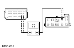
- Connect the air bag simulators to the sub-harnesses in place of the driver air bag module at the top of the steering column.
- Disconnect the passenger air bag module electrical connectors.
REFER to: Passenger Air Bag Module (501-20 Supplemental Restraint System, Removal and Installation).
- Connect the air bag simulators to the wiring harnesses in place of the passenger air bag module.
- Disconnect the side air curtain module electrical connector on both sides.
REFER to: Side Air Curtain Module (501-20 Supplemental Restraint System, Removal and Installation).
- Connect the air bag simulators to the wiring harnesses in place of the side air curtain modules.
- Disconnect the driver underseat air bag electrical connector.
- Connect the air bag simulator to the driver underseat air bag electrical connector in place of the safety belt pretensioner and side air bag module.
- Disconnect the passenger underseat air bag electrical connector.
- Connect the air bag simulator to the passenger underseat air bag electrical connector in place of the safety belt pretensioner and side air bag.
- Connect the battery ground cable.
REFER to: Battery Disconnect (414-01 Battery, Mounting and Cables, General Procedures).
Reactivation WARNING:The air bag simulators must be removed and the air bag modules reconnected when reactivated to avoid non-deployment in a collision. Failure to follow this instruction may result in personal injury. - Disconnect the battery ground cable.
REFER to: Battery Disconnect (414-01 Battery, Mounting and Cables, General Procedures).
- Wait at least one minute for the backup power supply in the restraints control module to deplete its stored energy.
- Remove the driver air bag simulators from the sub-harnesses at the top of the steering column.
- Connect and install the driver air bag module.
REFER to: Driver Air Bag Module (501-20 Supplemental Restraint System, Removal and Installation).
- Remove the passenger air bag simulators from the passenger air bag module harnesses.
- Connect and install the passenger air bag module.
REFER to: Passenger Air Bag Module (501-20 Supplemental Restraint System, Removal and Installation).
- Remove the side air curtain simulators from the side air curtain module wiring harnesses.
- Connect and install the side air curtain modules.
REFER to: Side Air Curtain Module (501-20 Supplemental Restraint System, Removal and Installation).
- Remove the driver underseat air bag simulator.
- Connect the driver underseat air bag electrical connector.
- Remove the passenger underseat air bag simulator.
- Connect the passenger underseat air bag electrical connector.
- Connect the battery ground cable.
REFER to: Battery Disconnect (414-01 Battery, Mounting and Cables, General Procedures).
Glossary Air Bag Simulator Air bag simulators are used to simulate air bag module connections to the system. Deactivate the System Deactivate the system means to carry out the deactivation procedure. REFER to Deactivation in this section. Prove Out the System The air bag warning indicator will illuminate for three seconds. If there is a fault condition, the air bag warning indicator will stay illuminated or illuminate after a five second delay. Reactivate the System Reactivate the system means to carry out the reactivation procedure. REFER to Reactivation in this section. Principles of Operation Supplemental Restraint System (SRS) Operation The vehicle is equipped with a DC fired sensing system. In the event of a severe frontal or three-quarter frontal impact, in excess of a predetermined limit the driver and passenger front air bags and safety belt buckle pretensioners will deploy. In the event of a severe full side impact, in excess of a predetermined limit either the driver or passenger side air bag, side air curtain (if equipped) and both safety belt buckle pretensioners will deploy. Air bag deployment will only occur, in the event of a severe collision when the ignition key is in the RUN position. The passenger air bag disable (PAD) switch (if equipped) will deactivate the passenger air bag, passenger safety belt buckle pretensioner and passenger side air bag in the event of a severe frontal or side impact; it will not deactivate the passenger side air curtain. Restraints control module The restraints control module retains full control of the whole system, providing continual system checks and full diagnostic capabilities. The non-volatile memory stores the fault codes, which can then be downloaded through the data link connector (DLC) to WDS. In the event of a failure in the vehicle supply during an accident, the restraints control module provides a backup power supply, sufficient to deploy the air bag(s) for a minimum of 150 ms. The backup power supply is discharged by the restraints control module within 60 seconds of the battery ground cable being disconnected. Thus making sure the supplemental restraint system remains operational. The restraints control module contains electronic acceleration sensors which measure the longitudinal acceleration and the lateral acceleration and provide both signals to the micro-controller proportional to the amount of acceleration measured. When these sensors sense an impact in excess of a predetermined limit, and the crash sensor or side impact sensor sends a signal to the restrains control module, the restraints control module initiates the circuit to deploy the air bag(s). The restraints control module also contains a safing sensor which enables the front air bags and the safety belt buckle pretensioners in the event of a front impact. The safing sensor also prevents unintentional deployment of the front air bags and safety belt buckle pretensioners in the event of a fault in the electronic acceleration sensor(s). Front Crash Sensor The front crash sensor contains an acceleration sensor, filter, amplifier and an application specific integrated circuit for signal transmitting and is mounted on the hood latch panel. The front crash sensor sends a signal at a level determined by the crash severity to the restraints control module. The restraints control module will evaluate the signal against stored data and deploy the frontal air bags and safety belt buckle pretensioners if required. Both the front crash sensor and the internal restraints control module longitudinal acceleration sensor must exceed a preset limit to initiate the air bag. Side Impact Sensor The side impact sensors are mounted at the base of the B-pillar on either side of the vehicle, to facilitate remote lateral impact sensing. Each side impact sensor contains an acceleration sensor, filter, amplifier and an application specific integrated circuit for signal transmitting. In the event of an impact, in excess of a predetermined limit, the side impact sensor sends a signal at a level determined by the crash severity to the restraints control module. The restraints control module will evaluate the signal against stored data, to deploy the side air bag on the side the deployment request was initiated. Both the side impact sensor and the internal restraints control module lateral acceleration sensor must exceed a preset limit to initiate the air bag. The restraints control module retains control of the side air bags, side air curtains and safety belt buckle pretensioners. Air Bag Warning Indicator The air bag warning indicator is incorporated into the instrument cluster, together with the automatic detach detect circuit. The air bag warning indicator illuminates for three seconds at key ON. If the system self-tests OK the indicator extinguishes, if there is a fault condition, the air bag warning indicator will stay illuminated or illuminate after a five second delay. The system is designed to illuminate the air bag warning indicator continuously if the restraints control module circuit is broken, either by loss of power or ground supply, or module disconnect, or BUS failure. The restraints control module retaining bolts are part of the ground circuit. Diagnostic evaluation of the SRS can be made through the data link connector (DLC) and WDS to establish the nature of the concern. Once the DTC is known the appropriate course of action can be selected from the Symptom Chart. Inspection and Verification - Verify the customer concern by operating the system.
- Visually inspect for obvious signs of mechanical or electrical damage.
Visual Inspection Chart | Electrical | - Fuse(s)
- Electrical connector(s)
- Circuit(s)
- Wiring harness
- Air bag module(s)
| - If an obvious cause for an observed or reported concern is found, correct the cause (if possible) before proceeding to the next step.
- If the cause is not visually evident, connect the diagnostic tool to the data link connector and select the vehicle to be tested from the diagnostic tool menu.
- Retrieve the DTCs and refer to the Symptom Chart.
Symptom Chart NOTE:It is only allowed to repair circuits between connectors. If damage has occurred within a connector a new wiring harness must be installed. Connectors must not be disassembled. | Symptom | Possible Sources | Action | | No communication with the module | * DLC. * Circuit(s). * Restraints control module. | * | | DTC B1046: Driver side air curtain cross link to another firing circuit | * Circuit(s). | NOTE:Check for a matching ‘cross link to another firing circuit’ DTC before carrying out pinpoint test. * | | DTC B1047: Driver side air bag cross link to another firing circuit | * Circuit(s). | NOTE:Check for a matching ‘cross link to another firing circuit’ DTC before carrying out pinpoint test. * | | DTC B1048: Passenger air bag first stage cross link to another firing circuit | * Circuit(s). | NOTE:Check for a matching ‘cross link to another firing circuit’ DTC before carrying out pinpoint test. * | | DTC B1049: Passenger safety belt pretensioner cross link to another firing circuit | * Circuit(s). | NOTE:Check for a matching ‘cross link to another firing circuit’ DTC before carrying out pinpoint test. * | | DTC B104B: Driver side impact sensor cross link to another firing circuit | * Circuit(s). | NOTE:Check for a matching ‘cross link to another firing circuit’ DTC before carrying out pinpoint test. * | | DTC B104C: Passenger side impact sensor cross link to another firing circuit | * Circuit(s). | NOTE:Check for a matching ‘cross link to another firing circuit’ DTC before carrying out pinpoint test. * | | DTC B104D: Front crash sensor cross link to another firing circuit | * Circuit(s). | NOTE:Check for a matching ‘cross link to another firing circuit’ DTC before carrying out pinpoint test. * | | DTC B104E: Driver side impact sensor short to ground or battery | * Circuit(s). | NOTE:Check for a matching ‘cross link to another firing circuit’ DTC before carrying out pinpoint test. * | | DTC B104F: Passenger side impact sensor internal fault | * Side impact sensor. | * INSTALL a new side impact sensor.
REFER to: Side Impact Sensor (501-20 Supplemental Restraint System, Removal and Installation).
REPEAT the self-test, CLEAR the DTCs. | | DTC B1050: Passenger side impact sensor short to ground or battery | * Circuit(s). | * | | DTC B1051: Driver side impact sensor internal fault | * Side impact sensor. | * INSTALL a new side impact sensor.
REFER to: Side Impact Sensor (501-20 Supplemental Restraint System, Removal and Installation).
REPEAT the self-test, CLEAR the DTCs. | | DTC B1054: Driver safety belt pretensioner cross link to another firing circuit | * Circuit(s). | NOTE:Check for a matching ‘cross link to another firing circuit’ DTC before carrying out pinpoint test. * | | DTC B1055: Passenger side air bag cross link to another firing circuit | * Circuit(s). | NOTE:Check for a matching ‘cross link to another firing circuit’ DTC before carrying out pinpoint test. * | | DTC B1056: Passenger side air curtain cross link to another firing circuit | * Circuit(s). | NOTE:Check for a matching ‘cross link to another firing circuit’ DTC before carrying out pinpoint test. * | | DTC B1057: Driver air bag first stage cross link to another firing circuit | * Circuit(s). | NOTE:Check for a matching ‘cross link to another firing circuit’ DTC before carrying out pinpoint test. * | | DTC B1058: Driver air bag second stage cross link to another firing circuit | * Circuit(s). | NOTE:Check for a matching ‘cross link to another firing circuit’ DTC before carrying out pinpoint test. * | | DTC B1059: Passenger air bag second stage cross link to another firing circuit | * Circuit(s). | NOTE:Check for a matching ‘cross link to another firing circuit’ DTC before carrying out pinpoint test. * | | DTC B105A: Restraints control module crash counter full | * Restraints control module (RCM). | * INSTALL a new restraints control module.
REFER to: Restraints Control Module (RCM) (501-20 Supplemental Restraint System, Removal and Installation).
REPEAT the self-test, CLEAR the DTCs. | | DTC B1231: Longitudinal acceleration threshold exceeded | * Crash data memory full. | * Clear the data memory using WDS. REPEAT the self-test, CLEAR the DTCs. * The data memory can be cleared a maximum of five times. | | DTC B1317: Battery voltage high | * Charging system. | * Check the charging system.
REFER to: Charging System (414-00 Charging System - General Information, Diagnosis and Testing).
REPEAT the self-test, CLEAR the DTCs. | | DTC B1318: Battery voltage low | * Battery. * Charging system. * Circuit. | * | | DTC B1342: Restraints control module is defective | * Restraints control module (RCM). | * INSTALL a new restraints control module (RCM).
REFER to: Restraints Control Module (RCM) (501-20 Supplemental Restraint System, Removal and Installation).
REPEAT the self-test, CLEAR the DTCs. | | DTC B1868: Air bag warning indicator lamp circuit failure | * Instrument cluster. | * Check the instrument cluster.
REFER to: Instrument Cluster (413-01 Instrument Cluster, Diagnosis and Testing).
REPEAT the self-test, CLEAR the DTCs. | | DTC B1871: Passenger air bag deactivation module fault | * Mismatch between passenger air bag deactivation (PAD) indicator and switch circuit. | * | | DTC B1877: Driver safety belt pretensioner open circuit | * Driver safety belt pretensioner. * Circuit(s). | * | | DTC B1878: Driver safety belt pretensioner short to battery | * Driver safety belt pretensioner. * Circuit(s). | * | | DTC B1879: Driver safety belt pretensioner short to ground | * Driver safety belt pretensioner. * Circuit(s). | * | | DTC B1881: Passenger safety belt pretensioner open circuit | * Passenger safety belt pretensioner. * Circuit(s). | * | | DTC B1882: Passenger safety belt pretensioner short to battery | * Passenger safety belt pretensioner. * Circuit(s). | * | | DTC B1883: Passenger safety belt pretensioner short to ground | * Passenger safety belt pretensioner. * Circuit(s). | * | | DTC 1884: Passenger air bag deactivation (PAD) indicator inoperative | * Restraints control module (RCM). * Passenger air bag deactivation indicator. * Circuit(s). | * | | DTC B1885: Driver safety belt pretensioner low resistance | * Driver safety belt pretensioner. * Circuit(s). | * | | DTC B1886: Passenger safety belt pretensioner low resistance | * Passenger safety belt pretensioner. * Circuit(s). | * | | DTC B1890: Passenger air bag deactivation (PAD) indicator short to battery | * Passenger air bag deactivation indicator. * Circuit(s). | * | | DTC B1916: Driver air bag first stage short to battery | * Clockspring. * Circuit(s). | * | | DTC B1921: Air bag diagnostic monitor ground circuit open | * Restraints control module (RCM) internal fault. | * INSTALL a new restraints control module (RCM).
REFER to: Restraints Control Module (RCM) (501-20 Supplemental Restraint System, Removal and Installation).
REPEAT the self-test, CLEAR the DTCs. | | DTC B1925: Passenger air bag first stage short to battery | * Circuit(s). | * | | DTC B1932: Driver air bag first stage open circuit | * Driver air bag module. * Clockspring. * Circuit(s). | * | | DTC B1933: Passenger air bag first stage open circuit | * Passenger air bag module. * Circuit(s). | * | | DTC B1934: Driver air bag first stage circuit low resistance | * Driver air bag module. * Clockspring. * Circuit(s). | * | | DTC B1935: Passenger air bag first stage circuit low resistance | * Passenger air bag module. * Circuit(s). | * | | DTC B1936: Driver air bag first stage circuit short to ground | * Driver air bag module. * Clockspring. * Circuit(s). | * | | DTC B1938: Passenger air bag first stage circuit short to ground | * Passenger air bag module. * Circuit(s). | * | | DTC B1992: Driver side air bag circuit short to battery | * Driver side air bag module. * Circuit(s). | * | | DTC B1993: Driver side air bag circuit short to ground | * Driver side air bag module. * Circuit(s). | * | | DTC B1994: Driver side air bag circuit open circuit | * Driver side air bag module. * Circuit(s). | * | | DTC B1995: Driver side air bag circuit low resistance | * Driver side air bag module. * Circuit(s). | * | | DTC B1996: Passenger side air bag circuit short to battery | * Passenger side air bag module. * Circuit(s). | * | | DTC B1997: Passenger side air bag circuit short to ground | * Passenger side air bag module. * Circuit(s). | * | | DTC B1998: Passenger side air bag circuit open circuit | * Passenger side air bag module. * Circuit(s). | * | | DTC B1999: Passenger side air bag circuit low resistance | * Passenger side air bag module. * Circuit(s). | * | | DTC B2226: Front crash sensor internal fault | * Crash sensor. | * INSTALL a new crash sensor.
REFER to: Crash Sensor (501-20 Supplemental Restraint System, Removal and Installation).
REPEAT the self-test, CLEAR the DTCs. | | DTC B2227: Front crash sensor communications fault | * Crash sensor. * Restraints control module (RCM). * Circuit(s). | * | | DTC B2228: Driver air bag second stage circuit short to ground | * Driver air bag module. * Clockspring. * Circuit(s). | * | | DTC B2229: Passenger air bag second stage circuit short to ground | * Passenger air bag module. * Circuit(s). | * | | DTC B2230: Driver air bag second stage circuit short to battery | * Clockspring. * Circuit(s). | * | | DTC B2231: Passenger air bag second stage circuit short to battery | * Passenger air bag module. * Circuit(s). | * | | DTC B2232: Driver air bag second stage open circuit | * Driver air bag module. * Clockspring. * Circuit(s). | * | | DTC B2233: Passenger air bag second stage open circuit | * Passenger air bag module. * Circuit(s). | * | | DTC B2234: Driver air bag second stage circuit low resistance | * Driver air bag module. * Clockspring. * Circuit(s). | * | | DTC B2235: Passenger air bag second stage circuit low resistance | * Passenger air bag module. * Circuit(s). | * | | DTC B2432: Driver safety belt buckle switch circuit open circuit | * Driver safety belt buckle switch. * Circuit(s). | * | | DTC B2433: Driver safety belt buckle switch circuit short to battery | * Driver safety belt buckle switch. * Circuit(s). | * | | DTC B2434: Driver safety belt buckle switch circuit short to ground | * Driver safety belt buckle switch. * Circuit(s). | * | | DTC B2435: Driver safety belt buckle switch resistance out of range | * Driver safety belt buckle switch. * Circuit(s). | * | | DTC B2477: Restraints control module (RCM) configuration failure | * New restraints control module (RCM) incorrectly configured. | * CHECK model option content. CONFIGURE the restraints control module. For additional information, REFER to WDS. | | DTC B2773: Driver side air curtain circuit low resistance | * Driver side air curtain module. * Circuit(s). | * | | B2774: Driver side air curtain circuit open circuit | * Driver side air curtain module. * Circuit(s). | * | | B2775: Driver side air curtain circuit short to ground | * Driver side air curtain module. * Circuit(s). | * | | B2776: Driver side air curtain circuit short to battery | * Circuit(s). | * | | 2777: Passenger side air curtain circuit low resistance | * Passenger side air curtain module. * Circuit(s). | * | | DTC B2778: Passenger side air curtain circuit open circuit | * Passenger side air curtain module. * Circuit(s). | * | | DTC B2779: Passenger side air curtain circuit short to ground | * Passenger side air curtain module. * Circuit(s). | * | | DTC B2780: Passenger side air curtain circuit short to battery | * Circuit(s). | * | | DTC B2855: Front crash sensor circuit short to battery or ground | * Circuit(s). | * | | DTC B2856: Front crash sensor to restraints control module (RCM) mismatch | * Incorrect new crash sensor installed. | * INSTALL the correct crash sensor.
REFER to: Crash Sensor (501-20 Supplemental Restraint System, Removal and Installation).
REPEAT the self-test, CLEAR the DTCs. | | DTC B2886: Passenger side impact sensor to restraints control module (RCM) mismatch | * Incorrect new side impact sensor installed. | * INSTALL the correct side impact sensor.
REFER to: Side Impact Sensor (501-20 Supplemental Restraint System, Removal and Installation).
REPEAT the self-test, CLEAR the DTCs. | | DTC B2887: Driver side impact sensor to restraints control module (RCM) mismatch | * Incorrect new side impact sensor installed. | * INSTALL the correct side impact sensor.
REFER to: Side Impact Sensor (501-20 Supplemental Restraint System, Removal and Installation).
REPEAT the self-test, CLEAR the DTCs. | | DTC U0073: Control module communications bus off | * Circuit(s). | * | | DTC U1900: CAN Communications bus fault | * Circuit(s). | * | | DTC U2017: Driver side impact sensor communications fault | * Driver side impact sensor. * Restraints control module (RCM). * Circuit(s). | * | | DTC U2018: Passenger side impact sensor communications fault | * Passenger side impact sensor. * Restraints control module (RCM). * Circuit(s). | * GO to Pinpoint Test BR. GO to Pinpoint Test BR. | Pinpoint Tests | PINPOINT TEST A : NO COMMUNICATION WITH THE MODULE | | TEST CONDITIONS | DETAILS/RESULTS/ACTIONS | | A1: CHECK THAT WDS IS COMMUNICATING THROUGH THE DATA LINK CONNECTOR (DLC) | | | 1 Select an alternative system to check the DLC. | | | Is WDS able to communicate with the selected system? Yes No CHECK the DLC. For additional information, REFER to the Wiring Diagrams. | | A2: CHECK THE AIR BAG WARNING INDICATOR | | | 1 Ignition switch in position II. | | | 2 The air bag warning indicator should illuminate when the ignition is in the ON position for three seconds then go out. If a fault is present, the air bag warning indicator will illuminate after five seconds. | | | Is the air bag warning indicator operating? Yes No CHECK the instrument cluster.
REFER to: Instrument Cluster (413-01 Instrument Cluster, Diagnosis and Testing).
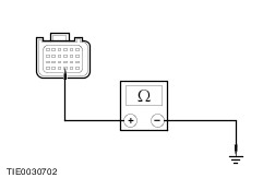
| | A3: CHECK THE DLC CIRCUIT | WARNING:To avoid accidental deployment, the restraints control module (RCM) backup power supply must be depleted. Wait at least one minute after disconnecting the battery ground cable(s) before commencing any repair or adjustment to the supplemental restraint system (SRS), or any component(s) adjacent to the SRS sensors. Failure to follow these instructions may result in personal injury. | | | 1 Ignition switch in position 0. | | | 2 Deactivate the supplemental restraint system. | | | 3 Disconnect Restraints Control Module C424. | | | 4 Measure the resistance between the: - DLC C200 pin 3, circuit 4-EC10A (GY) and the restraints control module C424 pin 19, circuit 4-EC10N (GY), harness side.
- DLC C200 pin 11, circuit 5-EC10A (BU) and the restraints control module C424 pin 20, circuit 5-EC10N (BU), harness side.
| | | Are the resistances less than 5 ohms? Yes If the air bag warning indicator is illuminated, INSTALL a new restraints control module.
REFER to: Restraints Control Module (RCM) (501-20 Supplemental Restraint System, Removal and Installation).
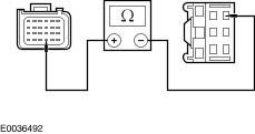
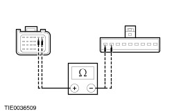
REPEAT the self-test, CLEAR the DTCs. REACTIVATE the system. No REPAIR circuit 4-EC10 (GY) or circuit 5-EC10 (BU). REPEAT the self-test, CLEAR the DTCs. REACTIVATE the system. | | PINPOINT TEST B : DTC B1046: DRIVER SIDE AIR CURTAIN CROSS LINK TO ANOTHER FIRING CIRCUIT | | TEST CONDITIONS | DETAILS/RESULTS/ACTIONS | | B1: CHECK THE DRIVER SIDE AIR CURTAIN CIRCUITS | WARNING:To avoid accidental deployment, the restraints control module (RCM) backup power supply must be depleted. Wait at least one minute after disconnecting the battery ground cable(s) before commencing any repair or adjustment to the supplemental restraint system (SRS), or any component(s) adjacent to the SRS sensors. Failure to follow these instructions may result in personal injury. | | | 1 Deactivate the supplemental restraint system. | | | 2 Disconnect Restraints Control Module C423. | | | 3 Disconnect Driver Side Air Curtain Simulator. | | | 4 Disconnect Inoperative Air Bag Module Simulator. | | | NOTE:Refer to the Wiring Diagrams for pin detail. 5 Measure the resistance between the: - restraints control module C423 pin 1, circuit 91S-JA50 (BK/RD), harness side and the inoperative air bag module circuits.
- restraints control module C423 pin 2, circuit 15S-JA50 (GN/OG), harness side and the inoperative air bag module circuits.
| | | Are the resistances greater than 10,000 ohms? Yes REPEAT the self-test, CLEAR the DTCs. REACTIVATE the system. No REPAIR the circuits. REPEAT the self-test, CLEAR the DTCs. REACTIVATE the system. | | PINPOINT TEST C : DTC B1047: DRIVER SIDE AIR BAG CROSS LINK TO ANOTHER FIRING CIRCUIT | | TEST CONDITIONS | DETAILS/RESULTS/ACTIONS | | C1: CHECK THE DRIVER SIDE AIR BAG CIRCUITS | WARNING:To avoid accidental deployment, the restraints control module (RCM) backup power supply must be depleted. Wait at least one minute after disconnecting the battery ground cable(s) before commencing any repair or adjustment to the supplemental restraint system (SRS), or any component(s) adjacent to the SRS sensors. Failure to follow these instructions may result in personal injury. | | | 1 Deactivate the supplemental restraint system. | | | 2 Disconnect Restraints Control Module C423. | | | 3 Disconnect Driver Underseat Air Bag Simulator. | | | 4 Disconnect Inoperative Air Bag Module Simulator. | | | NOTE:Refer to the Wiring Diagrams for pin detail. 5 Measure the resistance between the: - restraints control module C423 pin 19, circuit 91S-JA37 (BK/GN), harness side and the inoperative air bag module circuits.
- restraints control module C423 pin 20, circuit 15S-JA37 (GN/BK), harness side and the inoperative air bag module circuits.
| | | Are the resistances greater than 10,000 ohms? Yes REPEAT the self-test, CLEAR the DTCs. REACTIVATE the system. No REPAIR the circuits. REPEAT the self-test, CLEAR the DTCs. REACTIVATE the system. | | PINPOINT TEST D : DTC B1048: PASSENGER AIR BAG FIRST STAGE CROSS LINK TO ANOTHER FIRING CIRCUIT | | TEST CONDITIONS | DETAILS/RESULTS/ACTIONS | | D1: CHECK THE PASSENGER AIR BAG FIRST STAGE CIRCUITS | WARNING:To avoid accidental deployment, the restraints control module (RCM) backup power supply must be depleted. Wait at least one minute after disconnecting the battery ground cable(s) before commencing any repair or adjustment to the supplemental restraint system (SRS), or any component(s) adjacent to the SRS sensors. Failure to follow these instructions may result in personal injury. | | | 1 Deactivate the supplemental restraint system. | | | 2 Disconnect Restraints Control Module C424. | | | 3 Disconnect Passenger Air Bag First Stage Simulator. | | | 4 Disconnect Inoperative Air Bag Module Simulator. | | | NOTE:Refer to the Wiring Diagrams for pin detail. 5 Measure the resistance between the: - restraints control module C424 pin 10, circuit 91S-JA31 (BK/WH), harness side and the inoperative air bag module circuits.
- restraints control module C424 pin 9, circuit 15S-JA31 (GN/WH), harness side and the inoperative air bag module circuits.
| | | Are the resistances greater than 10,000 ohms? Yes REPEAT the self-test, CLEAR the DTCs. REACTIVATE the system. No REPAIR the circuits. REPEAT the self-test, CLEAR the DTCs. REACTIVATE the system. | | PINPOINT TEST E : DTC B1049: PASSENGER SAFETY BELT PRETENSIONER CROSS LINK TO ANOTHER FIRING CIRCUIT | | TEST CONDITIONS | DETAILS/RESULTS/ACTIONS | | E1: CHECK THE PASSENGER SAFETY BELT PRETENSIONER CIRCUITS | WARNING:To avoid accidental deployment, the restraints control module (RCM) backup power supply must be depleted. Wait at least one minute after disconnecting the battery ground cable(s) before commencing any repair or adjustment to the supplemental restraint system (SRS), or any component(s) adjacent to the SRS sensors. Failure to follow these instructions may result in personal injury. | | | 1 Deactivate the supplemental restraint system. | | | 2 Disconnect Restraints Control Module C423. | | | 3 Disconnect Passenger Underseat Air Bag Simulator. | | | 4 Disconnect Inoperative Air Bag Module Simulator. | | | NOTE:Refer to the Wiring Diagrams for pin detail. 5 Measure the resistance between the: - restraints control module C423 pin 10, circuit 91S-JA34 (BK/RD), harness side and the inoperative air bag module circuits.
- restraints control module C423 pin 9, circuit 15S-JA34 (GN/OG), harness side and the inoperative air bag module circuits.
| | | Are the resistances greater than 10,000 ohms? Yes REPEAT the self-test, CLEAR the DTCs. REACTIVATE the system. No REPAIR the circuits. REPEAT the self-test, CLEAR the DTCs. REACTIVATE the system. | | PINPOINT TEST F : DTC B104B: DRIVER SIDE IMPACT SENSOR CROSS LINK TO ANOTHER FIRING CIRCUIT | | TEST CONDITIONS | DETAILS/RESULTS/ACTIONS | | F1: CHECK THE DRIVER SIDE IMPACT SENSOR CIRCUITS | WARNING:To avoid accidental deployment, the restraints control module (RCM) backup power supply must be depleted. Wait at least one minute after disconnecting the battery ground cable(s) before commencing any repair or adjustment to the supplemental restraint system (SRS), or any component(s) adjacent to the SRS sensors. Failure to follow these instructions may result in personal injury. | | | 1 Deactivate the supplemental restraint system. | | | 2 Disconnect Restraints Control Module C423. | | | 3 Disconnect Driver Side Impact Sensor. | | | 4 Disconnect Inoperative Air Bag Module Simulator. | | | NOTE:Refer to the Wiring Diagrams for pin detail. 5 Measure the resistance between the: - restraints control module C423 pin 27, circuit 9-JA39 (BN), harness side and the inoperative air bag module circuits.
- restraints control module C423 pin 26, circuit 8-JA39 (WH), harness side and the inoperative air bag module circuits.
| | | Are the resistances greater than 10,000 ohms? Yes REPEAT the self-test, CLEAR the DTCs. REACTIVATE the system. No REPAIR the circuits. REPEAT the self-test, CLEAR the DTCs. REACTIVATE the system. | | PINPOINT TEST G : DTC B104C: PASSENGER SIDE IMPACT SENSOR CROSS LINK TO ANOTHER FIRING CIRCUIT | | TEST CONDITIONS | DETAILS/RESULTS/ACTIONS | | G1: CHECK THE PASSENGER SIDE IMPACT SENSOR CIRCUITS | WARNING:To avoid accidental deployment, the restraints control module (RCM) backup power supply must be depleted. Wait at least one minute after disconnecting the battery ground cable(s) before commencing any repair or adjustment to the supplemental restraint system (SRS), or any component(s) adjacent to the SRS sensors. Failure to follow these instructions may result in personal injury. | | | 1 Deactivate the supplemental restraint system. | | | 2 Disconnect Restraints Control Module C423. | | | 3 Disconnect Passenger Side Impact Sensor. | | | 4 Disconnect Inoperative Air Bag Module Simulator. | | | NOTE:Refer to the Wiring Diagrams for pin detail. 5 Measure the resistance between the: - restraints control module C423 pin 28, circuit 9-JA40 (BN/WH), harness side and the inoperative air bag module circuits.
- restraints control module C423 pin 29, circuit 8-JA40 (WH/VT), harness side and the inoperative air bag module circuits.
| | | Are the resistances greater than 10,000 ohms? Yes REPEAT the self-test, CLEAR the DTCs. REACTIVATE the system. No REPAIR the circuits. REPEAT the self-test, CLEAR the DTCs. REACTIVATE the system. | | PINPOINT TEST H : DTC B104D: CRASH SENSOR CROSS LINK TO ANOTHER FIRING CIRCUIT | | TEST CONDITIONS | DETAILS/RESULTS/ACTIONS | | H1: CHECK THE CRASH SENSOR CIRCUITS | WARNING:To avoid accidental deployment, the restraints control module (RCM) backup power supply must be depleted. Wait at least one minute after disconnecting the battery ground cable(s) before commencing any repair or adjustment to the supplemental restraint system (SRS), or any component(s) adjacent to the SRS sensors. Failure to follow these instructions may result in personal injury. | | | 1 Deactivate the supplemental restraint system. | | | 2 Disconnect Restraints Control Module C424. | | | 3 Disconnect Crash Sensor C420. | | | 4 Disconnect Inoperative Air Bag Module Simulator. | | | NOTE:Refer to the Wiring Diagrams for pin detail. 5 Measure the resistance between the: - restraints control module C424 pin 13, circuit 9-JA49 (BN), harness side and the inoperative air bag module circuits.
- restraints control module C424 pin 14, circuit 8-JA49 (WH), harness side and the inoperative air bag module circuits.
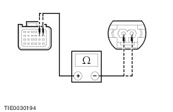
| | | Are the resistances greater than 10,000 ohms? Yes REPEAT the self-test, CLEAR the DTCs. REACTIVATE the system. No REPAIR the circuits. REPEAT the self-test, CLEAR the DTCs. REACTIVATE the system. | | PINPOINT TEST I : DTC B104E: DRIVER SIDE IMPACT SENSOR SHORT TO GROUND OR BATTERY | | TEST CONDITIONS | DETAILS/RESULTS/ACTIONS | | I1: DTC B104E: CHECK THE DRIVER SIDE IMPACT SENSOR CIRCUITS | WARNING:To avoid accidental deployment, the restraints control module (RCM) backup power supply must be depleted. Wait at least one minute after disconnecting the battery ground cable(s) before commencing any repair or adjustment to the supplemental restraint system (SRS), or any component(s) adjacent to the SRS sensors. Failure to follow these instructions may result in personal injury. | | | 1 Deactivate the supplemental restraint system. | | | 2 Disconnect Restraints Control Module C423. | | | 3 Disconnect Driver Side Impact Sensor C427. | | | 4 Measure the resistance between the: - restraints control module C423 pin 26, circuit 8-JA39 (WH), harness side and the driver side impact sensor C427 pin 1, circuit 8-JA39 (WH), harness side.
- restraints control module C423 pin 27, circuit 9-JA39 (BN), harness side and the driver side impact sensor C427 pin 2, circuit 9-JA39 (BN), harness side.
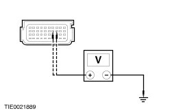
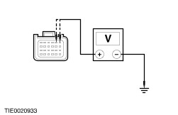
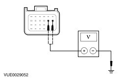
| | | Are the resistances less than 5 ohms? Yes No REPAIR circuit 8-JA39 (WH) or circuit 9-JA39 (BN). REPEAT the self-test, CLEAR the DTCs. REACTIVATE the system. | | I2: CHECK THE DRIVER SIDE IMPACT SENSOR FOR SHORT TO BATTERY | | | 1 Ignition switch in position II. | | | 2 Measure the voltage between the: - restraints control module C423 pin 26, circuit 8-JA39 (WH), harness side and ground.
- restraints control module C423 pin 27, circuit 9-JA39 (BN), harness side and ground.
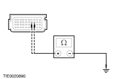
| | | Is any voltage present? Yes REPAIR circuit 8-JA39 (WH) or circuit 9-JA39 (BN). REPEAT the self-test, CLEAR the DTCs. REACTIVATE the system. No | | I3: CHECK THE DRIVER SIDE IMPACT SENSOR FOR SHORT TO GROUND | | | 1 Ignition switch in position 0. | | | 2 Measure the resistance between the: - restraints control module C423 pin 26, circuit 8-JA39 (WH), harness side and ground.
- restraints control module C423 pin 27, circuit 9-JA39 (BN), harness side and ground.
| | | Are the resistances less than 5 ohms? Yes REPEAT the self-test, CLEAR the DTCs. REACTIVATE the system. No REPAIR the circuit 8-JA39 (WH) or circuit 9-JA39 (BN). REPEAT the self-test, CLEAR the DTCs. REACTIVATE the system. | | PINPOINT TEST J : DTC B1050: PASSENGER SIDE IMPACT SENSOR SHORT TO GROUND OR BATTERY | | TEST CONDITIONS | DETAILS/RESULTS/ACTIONS | | J1: CHECK THE PASSENGER SIDE IMPACT SENSOR CIRCUITS | WARNING:To avoid accidental deployment, the restraints control module (RCM) backup power supply must be depleted. Wait at least one minute after disconnecting the battery ground cable(s) before commencing any repair or adjustment to the supplemental restraint system (SRS), or any component(s) adjacent to the SRS sensors. Failure to follow these instructions may result in personal injury. | | | 1 Deactivate the supplemental restraint system. | | | 2 Disconnect Restraints Control Module C423. | | | 3 Disconnect Passenger Side Impact Sensor C428. | | | 4 Measure the resistance between the: - restraints control module C423 pin 28, circuit 8-JA40 (WH/VT), harness side and the driver side impact sensor C428 pin 1, circuit 8-JA40 (WH/VT), harness side.
- restraints control module C423 pin 29, circuit 9-JA40 (BN/WH), harness side and the driver side impact sensor C428 pin 2, circuit 9-JA40 (BN/WH), harness side.
| | | Are the resistances less than 5 ohms? Yes No REPAIR the circuit 8-JA40 (WH/VT) or circuit 9-JA40 (BN/WH). REPEAT the self-test, CLEAR the DTCs. REACTIVATE the system. | | J2: CHECK THE PASSENGER SIDE IMPACT SENSOR FOR SHORT TO BATTERY | | | 1 Ignition switch in position II. | | | 2 Measure the voltage between the: - restraints control module C423 pin 28, circuit 8-JA40 (WH/VT), harness side and ground.
- restraints control module C423 pin 29, circuit 9-JA40 (BN/WH), harness side and ground.
| | | Is any voltage present? Yes REPAIR the circuit 8-JA40 (WH/VT) or circuit 9-JA40 (BN/WH). REPEAT the self-test, CLEAR the DTCs. REACTIVATE the system. No | | J3: CHECK THE PASSENGER SIDE IMPACT SENSOR FOR SHORT TO GROUND | | | 1 Ignition switch in position 0. | | | 2 Measure the resistance between the: - restraints control module C423 pin 28, circuit 8-JA40 (WH/VT), harness side and ground.
- restraints control module C423 pin 29, circuit 9-JA40 (BN/WH), harness side and ground.
| | | Are the resistances less than 5 ohms? Yes REPEAT the self-test, CLEAR the DTCs. REACTIVATE the system. No REPAIR the circuit 8-JA40 (WH/VT) or circuit 9-JA40 (BN/WH). REPEAT the self-test, CLEAR the DTCs. REACTIVATE the system. | | PINPOINT TEST K : DTC B1054: DRIVER SAFETY BELT PRETENSIONER CROSS LINK TO ANOTHER FIRING CIRCUIT | | TEST CONDITIONS | DETAILS/RESULTS/ACTIONS | | K1: CHECK THE DRIVER SAFETY BELT PRETENSIONER CIRCUITS | WARNING:To avoid accidental deployment, the restraints control module (RCM) backup power supply must be depleted. Wait at least one minute after disconnecting the battery ground cable(s) before commencing any repair or adjustment to the supplemental restraint system (SRS), or any component(s) adjacent to the SRS sensors. Failure to follow these instructions may result in personal injury. | | | 1 Deactivate the supplemental restraint system. | | | 2 Disconnect Restraints Control Module C423. | | | 3 Disconnect Driver Underseat Air Bag Simulator. | | | 4 Disconnect Inoperative Air Bag Module Simulator. | | | NOTE:Refer to the Wiring Diagrams for pin detail. 5 Measure the resistance between the: - restraints control module C423 pin 18, circuit 91S-JA33 (BK/BU), harness side and the inoperative air bag module circuits.
- restraints control module C423 pin 17, circuit 15S-JA33 (GN/BU), harness side and the inoperative air bag module circuits.
| | | Are the resistances greater than 10,000 ohms? Yes REPEAT the self-test, CLEAR the DTCs. REACTIVATE the system. No REPAIR the circuits. REPEAT the self-test, CLEAR the DTCs. REACTIVATE the system. | | PINPOINT TEST L : DTC B1055: PASSENGER SIDE AIR BAG CROSS LINK TO ANOTHER FIRING CIRCUIT | | TEST CONDITIONS | DETAILS/RESULTS/ACTIONS | | L1: CHECK THE PASSENGER SIDE AIR BAG CIRCUITS | WARNING:To avoid accidental deployment, the restraints control module (RCM) backup power supply must be depleted. Wait at least one minute after disconnecting the battery ground cable(s) before commencing any repair or adjustment to the supplemental restraint system (SRS), or any component(s) adjacent to the SRS sensors. Failure to follow these instructions may result in personal injury. | | | 1 Deactivate the supplemental restraint system. | | | 2 Disconnect Restraints Control Module C423. | | | 3 Disconnect Passenger Underseat Air Bag Simulator. | | | 4 Disconnect Inoperative Air Bag Module Simulator. | | | NOTE:Refer to the Wiring Diagrams for pin detail. 5 Measure the resistance between the: - restraints control module C423 pin 8, circuit 91S-JA38 (BK/RD), harness side and the inoperative air bag module circuits.
- restraints control module C423 pin 7, circuit 15S-JA38 (GN/OG), harness side and the inoperative air bag module circuits.
| | | Are the resistances greater than 10,000 ohms? Yes REPEAT the self-test, CLEAR the DTCs. REACTIVATE the system. No REPAIR the circuits. REPEAT the self-test, CLEAR the DTCs. REACTIVATE the system. | | PINPOINT TEST M : DTC B1056: PASSENGER SIDE AIR CURTAIN CROSS LINK TO ANOTHER FIRING CIRCUIT | | TEST CONDITIONS | DETAILS/RESULTS/ACTIONS | | M1: CHECK THE PASSENGER SIDE AIR CURTAIN CIRCUITS | WARNING:To avoid accidental deployment, the restraints control module (RCM) backup power supply must be depleted. Wait at least one minute after disconnecting the battery ground cable(s) before commencing any repair or adjustment to the supplemental restraint system (SRS), or any component(s) adjacent to the SRS sensors. Failure to follow these instructions may result in personal injury. | | | 1 Deactivate the supplemental restraint system. | | | 2 Disconnect Restraints Control Module C423. | | | 3 Disconnect Passenger Side Air Curtain Simulator. | | | 4 Disconnect Inoperative Air Bag Module Simulator. | | | NOTE:Refer to the Wiring Diagrams for pin detail. 5 Measure the resistance between the: - restraints control module C423 pin 11, circuit 91S-JA51 (BK/BU), harness side and the inoperative air bag module circuits.
- restraints control module C423 pin 12, circuit 15S-JA51 (GN/BU), harness side and the inoperative air bag module circuits.
| | | Are the resistances greater than 10,000 ohms? Yes REPEAT the self-test, CLEAR the DTCs. REACTIVATE the system. No REPAIR the circuits. REPEAT the self-test, CLEAR the DTCs. REACTIVATE the system. | | PINPOINT TEST N : DTC B1057: DRIVER AIR BAG FIRST STAGE CROSS LINK TO ANOTHER FIRING CIRCUIT | | TEST CONDITIONS | DETAILS/RESULTS/ACTIONS | | N1: CHECK THE DRIVER AIR BAG FIRST STAGE CIRCUITS | WARNING:To avoid accidental deployment, the restraints control module (RCM) backup power supply must be depleted. Wait at least one minute after disconnecting the battery ground cable(s) before commencing any repair or adjustment to the supplemental restraint system (SRS), or any component(s) adjacent to the SRS sensors. Failure to follow these instructions may result in personal injury. | | | 1 Deactivate the supplemental restraint system. | | | 2 Disconnect Restraints Control Module C424. | | | 3 Disconnect Driver Air Bag First Stage Simulator. | | | 4 Disconnect Inoperative Air Bag Module Simulator. | | | NOTE:Refer to the Wiring Diagrams for pin detail. 5 Measure the resistance between the: - restraints control module C424 pin 4, circuit 91S-JA8 (BK/OG), harness side and the inoperative air bag module circuits.
- restraints control module C424 pin 3, circuit 15S-JA8 (GN/RD), harness side and the inoperative air bag module circuits.
| | | Are the resistances greater than 10,000 ohms? Yes REPEAT the self-test, CLEAR the DTCs. REACTIVATE the system. No REPAIR the circuits. REPEAT the self-test, CLEAR the DTCs. REACTIVATE the system. | | PINPOINT TEST O : DTC B1058: DRIVER AIR BAG SECOND STAGE CROSS LINK TO ANOTHER FIRING CIRCUIT | | TEST CONDITIONS | DETAILS/RESULTS/ACTIONS | | O1: CHECK THE DRIVER AIR BAG SECOND STAGE CIRCUITS | WARNING:To avoid accidental deployment, the restraints control module (RCM) backup power supply must be depleted. Wait at least one minute after disconnecting the battery ground cable(s) before commencing any repair or adjustment to the supplemental restraint system (SRS), or any component(s) adjacent to the SRS sensors. Failure to follow these instructions may result in personal injury. | | | 1 Deactivate the supplemental restraint system. | | | 2 Disconnect Restraints Control Module C424. | | | 3 Disconnect Driver Air Bag Second Stage Simulator. | | | 4 Disconnect Inoperative Air Bag Module Simulator. | | | NOTE:Refer to the Wiring Diagrams for pin detail. 5 Measure the resistance between the: - restraints control module C424 pin 1, circuit 91S-JA48 (BK/GN), harness side and the inoperative air bag module circuits.
- restraints control module C424 pin 2, circuit 15S-JA48 (GN/BK), harness side and the inoperative air bag module circuits.
| | | Are the resistances greater than 10,000 ohms? Yes REPEAT the self-test, CLEAR the DTCs. REACTIVATE the system. No REPAIR the circuits. REPEAT the self-test, CLEAR the DTCs. REACTIVATE the system. | | PINPOINT TEST P : DTC B1059: PASSENGER AIR BAG SECOND STAGE CROSS LINK TO ANOTHER FIRING CIRCUIT | | TEST CONDITIONS | DETAILS/RESULTS/ACTIONS | | P1: CHECK THE PASSENGER AIR BAG SECOND STAGE CIRCUITS | WARNING:To avoid accidental deployment, the restraints control module (RCM) backup power supply must be depleted. Wait at least one minute after disconnecting the battery ground cable(s) before commencing any repair or adjustment to the supplemental restraint system (SRS), or any component(s) adjacent to the SRS sensors. Failure to follow these instructions may result in personal injury. | | | 1 Deactivate the supplemental restraint system. | | | 2 Disconnect Restraints Control Module C424. | | | 3 Disconnect Passenger Air Bag Second Stage Simulator. | | | 4 Disconnect Inoperative Air Bag Module Simulator. | | | NOTE:Refer to the Wiring Diagrams for pin detail. 5 Measure the resistance between the: - restraints control module C424 pin 7, circuit 91S-JA32 (BK/YE), harness side and the inoperative air bag module circuits.
- restraints control module C424 pin 8, circuit 15S-JA32 (GN/YE), harness side and the inoperative air bag module circuits.
| | | Are the resistances greater than 10,000 ohms? Yes REPEAT the self-test, CLEAR the DTCs. REACTIVATE the system. No REPAIR the circuits. REPEAT the self-test, CLEAR the DTCs. REACTIVATE the system. | | PINPOINT TEST Q : DTC B1318: BATTERY VOLTAGE LOW | | TEST CONDITIONS | DETAILS/RESULTS/ACTIONS | | Q1: CHECK THE BATTERY VOLTAGE | | | 1 Ignition switch in position II. | | | 2 Check the battery voltage with the ignition in the ON position. | | | Is the battery voltage greater than 8 volts? Yes No CHECK the battery and charging system.
REFER to: Charging System (414-00 Charging System - General Information, Diagnosis and Testing).
REPEAT the self-test CLEAR the DTCs. | | Q2: CHECK THE RESTRAINTS CONTROL MODULE SUPPLY CIRCUIT | WARNING:To avoid accidental deployment, the restraints control module (RCM) backup power supply must be depleted. Wait at least one minute after disconnecting the battery ground cable(s) before commencing any repair or adjustment to the supplemental restraint system (SRS), or any component(s) adjacent to the SRS sensors. Failure to follow these instructions may result in personal injury. | | | 1 Ignition switch in position 0. | | | 2 Deactivate the supplemental restraint system. | | | 3 Disconnect Restraints Control Module C424. | | | 4 Ignition switch in position II. | | | 5 Measure the voltage between the restraints control module C424 pin 24, circuit 15-JA10 (GN/OG), harness side. | | | Is the voltage greater than 10 volts? Yes No REPAIR circuit 15-JA10 (GN/OG). REPEAT the self-test. CLEAR the DTCs. REACTIVATE the system. | | Q3: CHECK THE RESTRAINTS CONTROL MODULE SUPPLY CIRCUIT | | | 1 Disconnect Fuse 65. | | | 2 Measure the resistance between the restraints control module C424 pin 24, circuit 15-JA10 (GN/OG), harness side and fuse 65, harness side. | | | Is the resistance less than 5 ohms? Yes REPEAT the self-test, CLEAR the DTCs. REACTIVATE the system. No REPAIR circuit 15-JA10 (GN/OG). REPEAT the self-test, CLEAR the DTCs. REACTIVATE the system. | | PINPOINT TEST R : DTC B1871: PASSENGER AIR BAG DEACTIVATION (PAD) MODULE FAULT | | TEST CONDITIONS | DETAILS/RESULTS/ACTIONS | | R1: CHECK FOR VOLTAGE TO THE PASSENGER AIR BAG DEACTIVATION (PAD) CONTROL SWITCH | | | 1 Ignition switch in position II. | | | 2 Operate the PAD control switch to the OFF position. | | | Does the PAD indicator LED illuminate? Yes No | | R2: CHECK FOR CONTINUITY BETWEEN THE AIR BAG CONTROL MODULE AND THE PAD CONTROL SWITCH | WARNING:To avoid accidental deployment, the restraints control module (RCM) backup power supply must be depleted. Wait at least one minute after disconnecting the battery ground cable(s) before commencing any repair or adjustment to the supplemental restraint system (SRS), or any component(s) adjacent to the SRS sensors. Failure to follow these instructions may result in personal injury. | | | 1 Ignition switch in position 0. | | | 2 Deactivate the supplemental restraint system. | | | 3 Disconnect Restraints Control Module C424. | | | 4 Operate the PAD control switch to the ON position. | | | 5 Measure the resistance between the restraints control module C424 pin 18, circuit 31S-JA31 (BK/WH), harness side and the PAD control switch C619 pin 6, harness side. | | | Is the resistance less than 5 ohms? Yes INSTALL a new PAD control switch.
REFER to: Passenger Air Bag Deactivation (PAD) Switch (501-20 Supplemental Restraint System, Removal and Installation).
REPEAT the self-test, CLEAR the DTCs. REACTIVATE the system. No REPAIR circuit 31S-JA31 (BK/WH). REPEAT the self-test, CLEAR the DTCs. REACTIVATE the system. | | R3: CHECK FOR CONTINUITY BETWEEN THE RESTRAINTS CONTROL MODULE AND GROUND | | | 1 Ignition switch in position 0. | | | 2 Deactivate the supplemental restraint system. | | | 3 Disconnect Restraints Control Module C424. | | | 4 Measure the resistance between the restraints control module C424 pin 21, circuit 31S-JA47 (BK/OG), harness side and ground. | | | Is the resistance less than 5 ohms? Yes CONFIGURE the PAD control switch, REFER to WDS. CLEAR the DTCs. REACTIVATE the system. No | | R4: CHECK FOR CONTINUITY BETWEEN THE AIR BAG THE RESTRAINTS CONTROL MODULE AND THE PAD CONTROL SWITCH | | | 1 Disconnect PAD Control Switch C619. | | | 2 Measure the resistance between the restraints control module C424 pin 21, circuit 31S-JA47 (BK/OG), harness side and the PAD control switch C619 pin 4, circuit 31S-JA47 (BK/OG), harness side. | | | Is the resistance less than 5 ohms? Yes No REPAIR circuit 31S-JA47 (BK/OG). REPEAT the self-test, CLEAR the DTCs. REACTIVATE the system. | | R5: CHECK FOR CONTINUITY BETWEEN THE PAD CONTROL SWITCH AND GROUND | | | 1 Measure the resistance between the PAD control switch C619 pin 5, circuit 31-JA47 (BK), harness side and ground. | | | Is the resistance less than 5 ohms? Yes INSTALL a new PAD control switch.
REFER to: Passenger Air Bag Deactivation (PAD) Switch (501-20 Supplemental Restraint System, Removal and Installation).
REPEAT the self-test, CLEAR the DTCs. REACTIVATE the system. No REPAIR circuit 31-JA47 (BK). REPEAT the self-test, CLEAR the DTCs. REACTIVATE the system. | | PINPOINT TEST S : DTC B1877: DRIVER SAFETY BELT PRETENSIONER OPEN CIRCUIT | | TEST CONDITIONS | DETAILS/RESULTS/ACTIONS | | S1: CHECK THE DRIVER SAFETY BELT PRETENSIONER CIRCUIT | WARNING:To avoid accidental deployment, the restraints control module (RCM) backup power supply must be depleted. Wait at least one minute after disconnecting the battery ground cable(s) before commencing any repair or adjustment to the supplemental restraint system (SRS), or any component(s) adjacent to the SRS sensors. Failure to follow these instructions may result in personal injury. | | | 1 Deactivate the supplemental restraint system. | | | 2 Ignition switch in position II. | | | 3 Carry out the self-test with the simulators installed. | | | Does the system prove out correctly? Yes No | | S2: PROVE OUT THE DRIVER SAFETY BELT PRETENSIONER CIRCUIT | | | 1 Ignition switch in position 0. | | | 2 Disconnect Driver Safety Belt Pretensioner Simulator. | | | 3 Connect Driver Safety Belt Pretensioner C30. | | | 4 Ignition switch in position II. | | | 5 Carry out the self-test. | | | Does the system prove out correctly? Yes REPEAT the self-test, CLEAR the DTCs. REACTIVATE the system. No INSTALL a new driver safety belt buckle and pretensioner.
REFER to: Safety Belt Buckle and Pretensioner (501-20 Safety Belt System, Removal and Installation).
REPEAT the self-test, CLEAR the DTCs. REACTIVATE the system. | | S3: CHECK THE DRIVER SAFETY BELT PRETENSIONER FOR OPEN CIRCUIT OR HIGH RESISTANCE | | | 1 Ignition switch in position 0. | | | 2 Disconnect Restraints Control Module C423. | | | 3 Disconnect Driver Safety Belt Pretensioner Simulator. | | | 4 Measure the resistance between the: - restraints control module C423 pin 17, circuit 15S-JA33 (GN/BU), harness side and the underseat connector C30 pin 7, circuit 15S-JA33 (GN/BU), harness side.
- restraints control module C423 pin 18, circuit 91S-JA33 (BK/BU), harness side and the underseat connector C30 pin 8, circuit 91S-JA33 (BK/BU), harness side.
| | | Are the resistances less than 5 ohms? Yes REPEAT the self-test, CLEAR the DTCs. REACTIVATE the system. No REPAIR circuit 15S-JA33 (GN/BU) or circuit 91S-JA33 (BK/BU). REPEAT the self-test, CLEAR the DTCs. REACTIVATE the system. | | PINPOINT TEST T : DTC B1878: DRIVER SAFETY BELT PRETENSIONER SHORT TO BATTERY | | TEST CONDITIONS | DETAILS/RESULTS/ACTIONS | | T1: CHECK THE DRIVER SAFETY BELT PRETENSIONER CIRCUIT | WARNING:To avoid accidental deployment, the restraints control module (RCM) backup power supply must be depleted. Wait at least one minute after disconnecting the battery ground cable(s) before commencing any repair or adjustment to the supplemental restraint system (SRS), or any component(s) adjacent to the SRS sensors. Failure to follow these instructions may result in personal injury. | | | 1 Deactivate the supplemental restraint system. | | | 2 Ignition switch in position II. | | | 3 Carry out the self-test with the simulators installed. | | | Does the system prove out correctly? Yes No | | T2: PROVE OUT THE DRIVER SAFETY BELT PRETENSIONER CIRCUIT | | | 1 Ignition switch in position 0. | | | 2 Disconnect Driver Safety Belt Pretensioner Simulator. | | | 3 Connect Driver Safety Belt Pretensioner C30. | | | 4 Ignition switch in position II. | | | 5 Carry out the self-test. | | | Does the system prove out correctly? Yes REPEAT the self-test, CLEAR the DTCs. REACTIVATE the system. No INSTALL a new driver safety belt buckle and pretensioner.
REFER to: Safety Belt Buckle and Pretensioner (501-20 Safety Belt System, Removal and Installation).
REPEAT the self-test, CLEAR the DTCs. REACTIVATE the system. | | T3: CHECK THE DRIVER SAFETY BELT PRETENSIONER CIRCUIT FOR A SHORT TO BATTERY | | | 1 Ignition switch in position 0. | | | 2 Disconnect Restraints Control Module C423. | | | 3 Disconnect Driver Safety Belt Pretensioner Simulator. | | | 4 Ignition switch in position II. | | | 5 Measure the voltage between the: - restraints control module C423 pin 17, circuit 15S-JA33 (GN/BU), harness side and ground.
- restraints control module C423 pin 18, circuit 91S-JA33 (BK/BU), harness side and ground.
| | | Is any voltage present? Yes REPAIR circuit 15S-JA33 (GN/BU) or circuit 91S-JA33 (BK/BU) and 15-JA10 (GN/OG). REPEAT the self-test, CLEAR the DTCs. REACTIVATE the system. No REPEAT the self-test, CLEAR the DTCs. REACTIVATE the system. | | PINPOINT TEST U : DTC B1879: DRIVER SAFETY BELT PRETENSIONER SHORT TO GROUND | | TEST CONDITIONS | DETAILS/RESULTS/ACTIONS | | U1: CHECK THE DRIVER SAFETY BELT PRETENSIONER CIRCUIT | WARNING:To avoid accidental deployment, the restraints control module (RCM) backup power supply must be depleted. Wait at least one minute after disconnecting the battery ground cable(s) before commencing any repair or adjustment to the supplemental restraint system (SRS), or any component(s) adjacent to the SRS sensors. Failure to follow these instructions may result in personal injury. | | | 1 Deactivate the supplemental restraint system. | | | 2 Ignition switch in position II. | | | 3 Carry out the self-test with the simulators installed. | | | Does the system prove out correctly? Yes No | | U2: PROVE OUT THE DRIVER SAFETY BELT PRETENSIONER CIRCUIT | | | 1 Ignition switch in position 0. | | | 2 Disconnect Driver Safety Belt Pretensioner Simulator. | | | 3 Connect Driver Safety Belt Pretensioner C30. | | | 4 Ignition switch in position II. | | | 5 Carry out the self-test. | | | Does the system prove out correctly? Yes REPEAT the self-test, CLEAR the DTCs. REACTIVATE the system. No INSTALL a new driver safety belt buckle and pretensioner.
REFER to: Safety Belt Buckle and Pretensioner (501-20 Safety Belt System, Removal and Installation).
REPEAT the self-test, CLEAR the DTCs. REACTIVATE the system. | | U3: CHECK THE DRIVER SAFETY BELT PRETENSIONER CIRCUIT FOR A SHORT TO GROUND | | | 1 Ignition switch in position 0. | | | 2 Disconnect Restraints Control Module C423. | | | 3 Disconnect Driver Safety Belt Pretensioner Simulator. | | | 4 Measure the resistance between the: - restraints control module C423 pin 17, circuit 15S-JA33 (GN/BU), harness side and ground.
- restraints control module C423 pin 18, circuit 91S-JA33 (BK/BU), harness side and ground.
| | | Are the resistances greater than 10,000 ohms? Yes REPEAT the self-test, CLEAR the DTCs. REACTIVATE the system. No REPAIR circuit 15S-JA33 (GN/BU) or circuit 91S-JA33 (BK/BU) and circuit 91-JA10 (BK/RD). REPEAT the self-test, CLEAR the DTCs. REACTIVATE the system. | | PINPOINT TEST V : DTC 1881: PASSENGER SAFETY BELT PRETENSIONER OPEN CIRCUIT | | TEST CONDITIONS | DETAILS/RESULTS/ACTIONS | | V1: CHECK THE PASSENGER SAFETY BELT PRETENSIONER CIRCUIT | WARNING:To avoid accidental deployment, the restraints control module (RCM) backup power supply must be depleted. Wait at least one minute after disconnecting the battery ground cable(s) before commencing any repair or adjustment to the supplemental restraint system (SRS), or any component(s) adjacent to the SRS sensors. Failure to follow these instructions may result in personal injury. | | | 1 Deactivate the supplemental restraint system. | | | 2 Ignition switch in position II. | | | 3 Carry out the self-test with the simulators installed. | | | Does the system prove out correctly? Yes No | | V2: PROVE OUT THE PASSENGER SAFETY BELT PRETENSIONER CIRCUIT | | | 1 Ignition switch in position 0. | | | 2 Disconnect Passenger Safety Belt Pretensioner Simulator. | | | 3 Connect Passenger Safety Belt Pretensioner C30. | | | 4 Ignition switch in position II. | | | 5 Carry out the self-test. | | | Does the system prove out correctly? Yes REPEAT the self-test, CLEAR the DTCs. REACTIVATE the system. No INSTALL a new passenger safety belt buckle and pretensioner.
REFER to: Safety Belt Buckle and Pretensioner (501-20 Safety Belt System, Removal and Installation).
REPEAT the self-test, CLEAR the DTCs. REACTIVATE the system. | | V3: CHECK THE PASSENGER SAFETY BELT PRETENSIONER FOR OPEN CIRCUIT OR HIGH RESISTANCE | | | 1 Ignition switch in position 0. | | | 2 Disconnect Restraints Control Module C423. | | | 3 Disconnect Passenger Safety Belt Pretensioner Simulator. | | | 4 Measure the resistance between the: - restraints control module C423 pin 10, circuit 15S-JA34 (GN/OG), harness side and the passenger underseat connector C31 pin 7, 15S-JA34 (GN/OG), harness side.
- restraints control module C423 pin 9, circuit 91S-JA34 (BK/RD), harness side and the passenger underseat connector C31 pin 8, 91S-JA34 (BK/RD), harness side.
| | | Are the resistances less than 5 ohms? Yes REPEAT the self-test, CLEAR the DTCs. REACTIVATE the system. No REPAIR circuits 15S-JA34 (GN/OG) or circuit 91S-JA34 (BK/RD). REPEAT the self-test, CLEAR the DTCs. REACTIVATE the system. | | PINPOINT TEST W : DTC B1882: PASSENGER SAFETY BELT PRETENSIONER SHORT TO BATTERY | | TEST CONDITIONS | DETAILS/RESULTS/ACTIONS | | W1: CHECK THE PASSENGER SAFETY BELT PRETENSIONER CIRCUIT | WARNING:To avoid accidental deployment, the restraints control module (RCM) backup power supply must be depleted. Wait at least one minute after disconnecting the battery ground cable(s) before commencing any repair or adjustment to the supplemental restraint system (SRS), or any component(s) adjacent to the SRS sensors. Failure to follow these instructions may result in personal injury. | | | 1 Deactivate the supplemental restraint system. | | | 2 Ignition switch in position II. | | | 3 Carry out the self-test with the simulators installed. | | | Does the system prove out correctly? Yes No | | W2: PROVE OUT THE PASSENGER SAFETY BELT PRETENSIONER CIRCUIT | | | 1 Ignition switch in position 0. | | | 2 Disconnect Passenger Safety Belt Pretensioner Simulator. | | | 3 Connect Passenger Safety Belt Pretensioner C30. | | | 4 Ignition switch in position II. | | | 5 Carry out the self-test. | | | Does the system prove out correctly? Yes REPEAT the self-test, CLEAR the DTCs. REACTIVATE the system. No INSTALL a new passenger safety belt buckle and pretensioner.
REFER to: Safety Belt Buckle and Pretensioner (501-20 Safety Belt System, Removal and Installation).
REPEAT the self-test, CLEAR the DTCs. REACTIVATE the system. | | W3: CHECK THE PASSENGER SAFETY BELT PRETENSIONER CIRCUIT FOR A SHORT TO BATTERY | | | 1 Ignition switch in position 0. | | | 2 Disconnect Restraints Control Module C423. | | | 3 Disconnect Passenger Safety Belt Pretensioner Simulator. | | | 4 Ignition switch in position II. | | | 5 Measure the voltage between the: - restraints control module C423 pin 10, circuit 15S-JA34 (GN/OG), harness side and ground.
- restraints control module C423 pin 9, circuit 91S-JA34 (BK/RD), harness side and ground.
| | | Is any voltage present? Yes REPAIR circuit 15-JA10 (GN/OG) and circuit 15S-JA34 (GN/OG) or circuit 91S-JA34 (BK/RD). REPEAT the self-test, CLEAR the DTCs. REACTIVATE the system. No REPEAT self-test. CLEAR the DTCs. REACTIVATE the system. | | PINPOINT TEST X : DTC B1883: PASSENGER SAFETY BELT PRETENSIONER SHORT TO GROUND | | TEST CONDITIONS | DETAILS/RESULTS/ACTIONS | | X1: CHECK THE PASSENGER SAFETY BELT PRETENSIONER CIRCUIT | WARNING:To avoid accidental deployment, the restraints control module (RCM) backup power supply must be depleted. Wait at least one minute after disconnecting the battery ground cable(s) before commencing any repair or adjustment to the supplemental restraint system (SRS), or any component(s) adjacent to the SRS sensors. Failure to follow these instructions may result in personal injury. | | | 1 Deactivate the supplemental restraint system. | | | 2 Ignition switch in position II. | | | 3 Carry out the self-test with the simulators installed. | | | Does the system prove out correctly? Yes No | | X2: PROVE OUT THE PASSENGER SAFETY BELT PRETENSIONER CIRCUIT | | | 1 Ignition switch in position 0. | | | 2 Disconnect Passenger Safety Belt Pretensioner Simulator. | | | 3 Connect Passenger Safety Belt Pretensioner C30. | | | 4 Ignition switch in position II. | | | 5 Carry out the self-test. | | | Does the system prove out correctly? Yes REPEAT the self-test, CLEAR the DTCs. REACTIVATE the system. No INSTALL a new passenger safety belt buckle and pretensioner.
REFER to: Safety Belt Buckle and Pretensioner (501-20 Safety Belt System, Removal and Installation).
REPEAT the self-test, CLEAR the DTCs. REACTIVATE the system. | | X3: CHECK THE PASSENGER SAFETY BELT PRETENSIONER CIRCUIT FOR A SHORT TO GROUND | | | 1 Ignition switch in position 0. | | | 2 Disconnect Restraints Control Module C423. | | | 3 Disconnect Passenger Safety Belt Pretensioner Simulator. | | | 4 Measure the resistance between the: - restraints control module C423 pin 10, circuit 15S-JA34 (GN/OG), harness side and ground.
- restraints control module C423 pin 9, circuit 91S-JA34 (BK/RD), harness side and ground.
| | | Are the resistances greater than 10,000 ohms? Yes REPEAT the self-test, CLEAR the DTCs. REACTIVATE the system. No REPAIR circuit 15S-JA34 (GN/0G) or circuit 91S-JA34 (BK/RD) and circuit 91-JA10 (BK/RD). REPEAT the self-test, CLEAR the DTCs. REACTIVATE the system. | | PINPOINT TEST Y : DTC B1884: PASSENGER AIR BAG DEACTIVATION (PAD) INDICATOR INOPERATIVE | | TEST CONDITIONS | DETAILS/RESULTS/ACTIONS | | Y1: CHECK FOR CONTINUITY BETWEEN THE RESTRAINTS CONTROL MODULE AND GROUND | WARNING:To avoid accidental deployment, the restraints control module (RCM) backup power supply must be depleted. Wait at least one minute after disconnecting the battery ground cable(s) before commencing any repair or adjustment to the supplemental restraint system (SRS), or any component(s) adjacent to the SRS sensors. Failure to follow these instructions may result in personal injury. | | | 1 Deactivate the supplemental restraint system. | | | 2 Disconnect Restraints Control Module C424. | | | 3 Disconnect PAD Indicator C453 or C455. | | | 4 Measure the resistance between the restraints control module C424 pin 17, circuit 91S-JA56 (BK/RD), harness side and ground. | | | Is the resistance greater than 10,000 ohms? Yes Vehicles with side air curtains GO to Y2. Vehicles without side air curtains GO to Y4. No REPAIR circuit 91S-JA56 (BK/RD). REPEAT the self-test, CLEAR the DTCs. REACTIVATE the system. | | Y2: CHECK FOR CONTINUITY BETWEEN THE PASSENGER AIR BAG DEACTIVATION (PAD) INDICATOR AND THE RESTRAINTS CONTROL MODULE (VEHICLES WITH SIDE AIR CURTAINS) | | | 1 Measure the resistance between the restraints control module C424 pin 17, circuit 91S-JA56 (BK/RD), harness side and the PAD indicator C455 pin 6, circuit 91S-JA56 (BK/RD), harness side. | | | Is the resistance less than 5 ohms? Yes No REPAIR circuit 91S-JA56 (BK/RD). REPEAT the self-test, CLEAR the DTCs. REACTIVATE the system. | | Y3: CHECK THE PAD INDICATOR SUPPLY CIRCUIT (VEHICLES WITH SIDE AIR CURTAINS) | | | 1 Measure the voltage between the PAD indicator C455 pin 3, circuit 15-JA56 (GN/OG), harness side and ground. | | | Is the voltage greater than 10 volts? Yes INSTALL a new PAD indicator. REPEAT the self-test, CLEAR the DTCs. REACTIVATE the system. No REPAIR circuit 15-JA56 (GN/OG). REPEAT the self-test, CLEAR the DTCs. REACTIVATE the system. | | Y4: CHECK FOR CONTINUITY BETWEEN THE PASSENGER AIR BAG DEACTIVATION (PAD) INDICATOR AND THE RESTRAINTS CONTROL MODULE (VEHICLES WITHOUT SIDE AIR CURTAINS) | | | 1 Measure the resistance between the restraints control module C424 pin 17, circuit 91S-JA56 (BK/RD), harness side and the PAD indicator C453 pin 2, circuit 91S-JA56 (BK/RD), harness side. | | | Is the resistance less than 5 ohms? Yes No REPAIR circuit 91S-JA56 (BK/RD). REPEAT the self-test, CLEAR the DTCs. REACTIVATE the system. | | Y5: CHECK THE PAD INDICATOR SUPPLY CIRCUIT (VEHICLES WITHOUT SIDE AIR CURTAINS) | | | 1 Measure the voltage between the PAD indicator C453 pin 5, circuit 15-JA56 (GN/OG), harness side and ground. | | | Is the voltage greater than 10 volts? Yes INSTALL a new PAD indicator. REPEAT the self-test, CLEAR the DTCs. REACTIVATE the system. No REPAIR circuit 15-JA56 (GN/OG). REPEAT the self-test, CLEAR the DTCs. REACTIVATE the system. | | PINPOINT TEST Z : DTC B1885: DRIVER SAFETY BELT PRETENSIONER LOW RESISTANCE | | TEST CONDITIONS | DETAILS/RESULTS/ACTIONS | | Z1: CHECK THE DRIVER SAFETY BELT PRETENSIONER CIRCUIT | WARNING:To avoid accidental deployment, the restraints control module (RCM) backup power supply must be depleted. Wait at least one minute after disconnecting the battery ground cable(s) before commencing any repair or adjustment to the supplemental restraint system (SRS), or any component(s) adjacent to the SRS sensors. Failure to follow these instructions may result in personal injury. | | | 1 Deactivate the supplemental restraint system. | | | 2 Ignition switch in position II. | | | 3 Carry out the self-test with the simulators installed. | | | Does the system prove out correctly? Yes No | | Z2: PROVE OUT THE DRIVER SAFETY BELT PRETENSIONER CIRCUIT | | | 1 Ignition switch in position 0. | | | 2 Disconnect Driver Safety Belt Pretensioner Simulator. | | | 3 Connect Driver Safety Belt Pretensioner C30. | | | 4 Ignition switch in position II. | | | 5 Carry out the self-test. | | | Does the system prove out correctly? Yes REPEAT the self-test, CLEAR the DTCs. REACTIVATE the system. No INSTALL a new driver safety belt buckle and pretensioner.
REFER to: Safety Belt Buckle and Pretensioner (501-20 Safety Belt System, Removal and Installation).
REPEAT the self-test, CLEAR the DTCs. REACTIVATE the system. | | Z3: CHECK THE DRIVER SAFETY BELT PRETENSIONER CIRCUIT FOR LOW RESISTANCE | | | 1 Ignition switch in position 0. | | | 2 Disconnect Restraints Control Module C423. | | | 3 Disconnect Driver Safety Belt Pretensioner Simulator. | | | 4 Measure the resistance between the restraints control module C423 pin 17, circuit 15S-JA33 (GN/BU) and pin 18, circuit 91S-JA33 (BK/BU), harness side. | | | Is the resistance greater than 10,000 ohms? Yes REPEAT the self-test, CLEAR the DTCs. REACTIVATE the system. No REPAIR circuit 15S-JA33 (GN/BU) and circuit 91S-JA33 (BK/BU). REPEAT the self-test, CLEAR the DTCs. REACTIVATE the system. | | PINPOINT TEST AA : DTC B1886: PASSENGER SAFETY BELT PRETENSIONER LOW RESISTANCE | | TEST CONDITIONS | DETAILS/RESULTS/ACTIONS | | AA1: CHECK THE PASSENGER SAFETY BELT PRETENSIONER CIRCUIT | WARNING:To avoid accidental deployment, the restraints control module (RCM) backup power supply must be depleted. Wait at least one minute after disconnecting the battery ground cable(s) before commencing any repair or adjustment to the supplemental restraint system (SRS), or any component(s) adjacent to the SRS sensors. Failure to follow these instructions may result in personal injury. | | | 1 Deactivate the supplemental restraint system. | | | 2 Ignition switch in position 0. | | | 3 Carry out the self-test with the simulators installed. | | | Does the system prove out correctly? Yes No | | AA2: PROVE OUT THE PASSENGER SAFETY BELT PRETENSIONER CIRCUIT | | | 1 Ignition switch in position 0. | | | 2 Disconnect Passenger Safety Belt Pretensioner Simulator. | | | 3 Connect Passenger Safety Belt Pretensioner C30. | | | 4 Ignition switch in position II. | | | 5 Carry out the self-test. | | | Does the system prove out correctly? Yes REPEAT the self-test, CLEAR the DTCs. REACTIVATE the system. No INSTALL a new passenger safety belt buckle and pretensioner.
REFER to: Safety Belt Buckle and Pretensioner (501-20 Safety Belt System, Removal and Installation).
REPEAT the self-test, CLEAR the DTCs. REACTIVATE the system. | | AA3: CHECK THE PASSENGER SAFETY BELT PRETENSIONER CIRCUIT FOR LOW RESISTANCE | | | 1 Ignition switch in position 0. | | | 2 Disconnect Restraints Control Module C423. | | | 3 Disconnect Passenger Safety Belt Pretensioner Simulator. | | | 4 Measure the resistance between the restraints control module C423 pin 10, circuit 15S-JA34 (GN/OG) and pin 9, circuit 91S-JA34 (BK/RD), harness side. | | | Is the resistance greater than 10,000 ohms? Yes REPEAT the self-test, CLEAR the DTCs. REACTIVATE the system. No REPAIR circuit 15S-JA34 (GN/OG) and circuit 91S-JA34 (BK/RD). REPEAT the self-test, CLEAR the DTCs. REACTIVATE the system. | | PINPOINT TEST AB : DTC B1890: PASSENGER AIR BAG DEACTIVATION (PAD) INDICATOR SHORT TO BATTERY | | TEST CONDITIONS | DETAILS/RESULTS/ACTIONS | | AB1: CHECK THE PAD INDICATOR TO RESTRAINTS CONTROL MODULE CIRCUIT | WARNING:To avoid accidental deployment, the restraints control module (RCM) backup power supply must be depleted. Wait at least one minute after disconnecting the battery ground cable(s) before commencing any repair or adjustment to the supplemental restraint system (SRS), or any component(s) adjacent to the SRS sensors. Failure to follow these instructions may result in personal injury. | | | 1 Deactivate the supplemental restraint system. | | | 2 Disconnect PAD Indicator C453 or C455. | | | 3 Disconnect Restraints Control Module C424. | | | 4 Measure the voltage between the restraints control module C424 pin 17, circuit 91S-JA56 (BK/RD), harness side and ground. | | | Is any voltage present? Yes REPAIR circuit 91S-JA56 (BK/RD). REPEAT the self-test, CLEAR the DTCs. REACTIVATE the system. No INSTALL a new PAD indicator. REPEAT the self-test, CLEAR the DTCs. REACTIVATE the system. | | PINPOINT TEST AC : DTC B1916: DRIVER AIR BAG FIRST STAGE SHORT TO BATTERY | | TEST CONDITIONS | DETAILS/RESULTS/ACTIONS | | AC1: CHECK THE DRIVER AIR BAG FIRST STAGE WIRING HARNESS FOR A SHORT TO BATTERY | WARNING:To avoid accidental deployment, the restraints control module (RCM) backup power supply must be depleted. Wait at least one minute after disconnecting the battery ground cable(s) before commencing any repair or adjustment to the supplemental restraint system (SRS), or any component(s) adjacent to the SRS sensors. Failure to follow these instructions may result in personal injury. | | | 1 Deactivate the supplemental restraint system. | | | 2 Disconnect Driver Air Bag Module First Stage Simulator. | | | 3 Disconnect Restraints Control Module C424. | | | 4 Ignition switch in position II. | | | 5 Measure the voltage between the: - restraints control module C424 pin 3, circuit 15S-JA8 (GN/RD), harness side and ground.
- restraints control module C424 pin 4, circuit 91S-JA8 (BK/OG), harness side and ground.
| | | Is any voltage present? Yes No CONNECT the driver air bag module first stage simulator and restraints control module. REPEAT the self-test, CLEAR the DTCs. REACTIVATE the system. | | AC2: CHECK THE CLOCKSPRING FOR A SHORT TO BATTERY | | | 1 Ignition switch in position 0. | | | 2 Disconnect Clockspring C896. | | | 3 Ignition switch in position II. | | | 4 Measure the voltage between the: - restraints control module C424 pin 3, circuit 15S-JA8 (GN/RD) harness side and ground.
- restraints control module C424 pin 4, circuit 91S-JA8 (BK/OG) harness side and ground.
| | | Is any voltage present? Yes REPAIR circuit 15S-JA8 (GN/RD) or circuit 91S-JA8 (BK/OG) and circuit 15-JA10 (GN/OG). REPEAT the self-test, CLEAR the DTCs. REACTIVATE the system. No INSTALL a new clockspring.
REFER to: Clockspring (501-20 Supplemental Restraint System, Removal and Installation).
REPEAT the self-test, CLEAR the DTCs. REACTIVATE the system. | | PINPOINT TEST AD : DTC B1925: PASSENGER AIR BAG FIRST STAGE SHORT TO BATTERY | | TEST CONDITIONS | DETAILS/RESULTS/ACTIONS | | AD1: CHECK THE PASSENGER AIR BAG CIRCUIT FOR A SHORT TO BATTERY | WARNING:To avoid accidental deployment, the restraints control module (RCM) backup power supply must be depleted. Wait at least one minute after disconnecting the battery ground cable(s) before commencing any repair or adjustment to the supplemental restraint system (SRS), or any component(s) adjacent to the SRS sensors. Failure to follow these instructions may result in personal injury. | | | 1 Deactivate the supplemental restraint system. | | | 2 Disconnect Passenger Air Bag Module First Stage Simulator. | | | 3 Disconnect Restraints Control Module C424. | | | 4 Ignition switch in position II. | | | 5 Measure the voltage between the: - restraints control module C424 pin 9, circuit 15S-JA31 (GN/WH) harness side and ground.
- restraints control module C424 pin 10, circuit 91S-JA31 (BK/WH) harness side and ground.
| | | Is any voltage present? Yes REPAIR circuit 15S-JA31 (GN/WH) and circuit 91S-JA31 (BK/WH). REPEAT the self-test, CLEAR the DTCs. REACTIVATE the system. No CONNECT the passenger air bag module first stage simulator and the restraints control module. REPEAT the self-test, CLEAR the DTCs. REACTIVATE the system. | | PINPOINT TEST AE : DTC B1932: DRIVER AIR BAG FIRST STAGE OPEN CIRCUIT | | TEST CONDITIONS | DETAILS/RESULTS/ACTIONS | | AE1: CHECK THE DRIVER AIR BAG FIRST STAGE CIRCUIT RESISTANCE | WARNING:To avoid accidental deployment, the restraints control module (RCM) backup power supply must be depleted. Wait at least one minute after disconnecting the battery ground cable(s) before commencing any repair or adjustment to the supplemental restraint system (SRS), or any component(s) adjacent to the SRS sensors. Failure to follow these instructions may result in personal injury. | | | 1 Deactivate the supplemental restraint system. | | | 2 Ignition switch in position II. | | | 3 Carry out the self-test with the simulators installed. | | | Does the system prove out correctly? Yes No | | AE2: CHECK THE DRIVER AIR BAG MODULE SQUIB RESISTANCE | WARNING:Do not proceed with this test unless using WDS. Failure to follow this instruction may result in personal injury. | | | 1 Connect the test and deployment lead to the driver air bag module - first stage. | | | 2 Select DMM specific on WDS. | | | 3 Connect the test and deployment lead to WDS. | | | 4 Measure the resistance of the air bag module squib. | | | 5 Connect the test and deployment lead to the driver air bag module - second stage. | | | 6 Measure the resistance of the air bag module squib. | | | Is the resistance between 2 and 3 ohms? Yes REPEAT the self-test, CLEAR the DTCs. REACTIVATE the system. No INSTALL a new driver air bag module.
REFER to: Driver Air Bag Module (501-20 Supplemental Restraint System, Removal and Installation).
REPEAT the self-test, CLEAR the DTCs. REACTIVATE the system. | | AE3: CHECK THE CLOCKSPRING FOR OPEN CIRCUIT OR HIGH RESISTANCE | | | 1 Ignition switch in position 0. | | | 2 Disconnect Restraints Control Module C424. | | | 3 Disconnect Clockspring C896. | | | 4 Measure the resistance between the: - restraints control module C424 pin 3, circuit 15S-JA8 (GN/RD), harness side and the clockspring C896 pin 1, circuit 15S-JA8 (GN/RD), harness side.
- restraints control module C424 pin 4, circuit 91S-JA8 (BK/OG), harness side and the clockspring C896 pin 2, circuit 91S-JA8 (BK/OG), harness side.
| | | Are the resistances less than 5 ohms? Yes Install a new clockspring.
REFER to: Clockspring (501-20 Supplemental Restraint System, Removal and Installation).
REPEAT the self-test, CLEAR the DTCs. REACTIVATE the system. No REPAIR circuit 15S-JA8 (GN/RD) or circuit 91S-JA8 (BK/OG). REPEAT the self-test, CLEAR the DTCs. REACTIVATE the system. | | PINPOINT TEST AF : DTC B1933: PASSENGER AIR BAG FIRST STAGE OPEN CIRCUIT | | TEST CONDITIONS | DETAILS/RESULTS/ACTIONS | | AF1: CHECK THE PASSENGER AIR BAG FIRST STAGE CIRCUIT RESISTANCE | WARNING:To avoid accidental deployment, the restraints control module (RCM) backup power supply must be depleted. Wait at least one minute after disconnecting the battery ground cable(s) before commencing any repair or adjustment to the supplemental restraint system (SRS), or any component(s) adjacent to the SRS sensors. Failure to follow these instructions may result in personal injury. | | | 1 Deactivate the supplemental restraint system. | | | 2 Ignition switch in position II. | | | 3 Carry out the self-test with the simulators installed. | | | Does the system prove out correctly? Yes No | | AF2: CHECK THE PASSENGER AIR BAG MODULE SQUIB RESISTANCE | WARNING:Do not proceed with this test unless using WDS. Failure to follow this instruction may result in personal injury. | | | 1 Connect the test and deployment lead to the passenger air bag module - first stage. | | | 2 Select DMM specific on WDS. | | | 3 Connect the test and deployment lead to WDS. | | | 4 Measure the resistance of the air bag module squib. | | | 5 Connect the test and deployment lead to the passenger air bag module - second stage. | | | 6 Measure the resistance of the air bag module squib. | | | Are the resistances between 2 and 3 ohms? Yes REPEAT the self-test, CLEAR the DTCs. REACTIVATE the system. No INSTALL a new passenger air bag module.
REFER to: Passenger Air Bag Module (501-20 Supplemental Restraint System, Removal and Installation).
REPEAT the self-test, CLEAR the DTCs. REACTIVATE the system. | | AF3: CHECK THE PASSENGER AIR BAG FIRST STAGE WIRING HARNESS FOR OPEN CIRCUIT OR HIGH RESISTANCE | | | 1 Ignition switch in position 0. | | | 2 Disconnect Restraints Control Module C424. | | | 3 Disconnect Passenger Air Bag First Stage Simulator. | | | 4 Measure the resistance between the: - restraints control module C424 pin 9, circuit 15S-JA31 (GN/WH), harness side and the passenger air bag module C425 pin 1, circuit 15S-JA31 (GN/WH), harness side.
- restraints control module C424 pin 10, circuit 91S-JA31 (BK/WH), harness side and the passenger air bag module C425 pin 2, circuit 91S-JA31 (BK/WH), harness side.
| | | Are the resistances less than 5 ohms? Yes REPEAT the self-test, CLEAR the DTCs. REACTIVATE the system. No REPAIR circuit 15S-JA31 (GN/WH) or circuit 91S-JA31 (BK/WH). REPEAT the self-test, CLEAR the DTCs. REACTIVATE the system. | | PINPOINT TEST AG : DTC B1934: DRIVER AIR BAG FIRST STAGE CIRCUIT LOW RESISTANCE | | TEST CONDITIONS | DETAILS/RESULTS/ACTIONS | | AG1: CHECK THE DRIVER AIR BAG FIRST STAGE CIRCUIT RESISTANCE | WARNING:To avoid accidental deployment, the air bag control module (RCM) backup power supply must be depleted. Wait at least one minute after disconnecting the battery ground cable(s) before commencing any repair or adjustment to the supplemental restraint system (SRS), or any component(s) adjacent to the SRS sensors. Failure to follow these instructions may result in personal injury. | | | 1 Deactivate the supplemental restraint system. | | | 2 Ignition switch in position II. | | | 3 Carry out the self-test with the simulators installed. | | | Does the system prove out correctly? Yes No | | AG2: CHECK THE DRIVER AIR BAG MODULE SQUIB RESISTANCE | WARNING:Do not proceed with this test unless using WDS. Failure to follow this instruction may result in personal injury. | | | 1 Connect the test and deployment lead to the driver air bag module - first stage. | | | 2 Select DMM specific on WDS. | | | 3 Connect the test and deployment lead to WDS. | | | 4 Measure the resistance of the air bag module squib. | | | 5 Connect the test and deployment lead to the driver air bag module - second stage. | | | 6 Measure the resistance of the air bag module squib. | | | Are the resistances between 2 and 3 ohms? Yes REPEAT the self-test, CLEAR the DTCs. REACTIVATE the system. No INSTALL a new driver air bag module.
REFER to: Driver Air Bag Module (501-20 Supplemental Restraint System, Removal and Installation).
REPEAT the self-test, CLEAR the DTCs. REACTIVATE the system. | | AG3: CHECK THE CLOCKSPRING FOR LOW RESISTANCE | | | 1 Ignition switch in position 0. | | | 2 Disconnect Restraints Control Module C424. | | | 3 Disconnect Clockspring C896. | | | 4 Measure the resistance between the restraints control module C424 pin 3, circuit 15S-JA8 (GN/RD) and pin 4, circuit 91S-JA8 (BK/OG), harness side. | | | Is the resistance greater than 10,000 ohms? Yes INSTALL a new clockspring.
REFER to: Clockspring (501-20 Supplemental Restraint System, Removal and Installation).
REPEAT the self-test, CLEAR the DTCs. REACTIVATE the system. No REPAIR circuit 15S-JA8 (GN/RD) and circuit 91S-JA8 (BK/OG). REPEAT the self-test, CLEAR the DTCs. REACTIVATE the system. | | PINPOINT TEST AH : DTC B1935: PASSENGER AIR BAG FIRST STAGE CIRCUIT LOW RESISTANCE | | TEST CONDITIONS | DETAILS/RESULTS/ACTIONS | | AH1: CHECK THE PASSENGER AIR BAG FIRST STAGE CIRCUIT RESISTANCE | WARNING:To avoid accidental deployment, the restraints control module (RCM) backup power supply must be depleted. Wait at least one minute after disconnecting the battery ground cable(s) before commencing any repair or adjustment to the supplemental restraint system (SRS), or any component(s) adjacent to the SRS sensors. Failure to follow these instructions may result in personal injury. | | | 1 Deactivate the supplemental restraint system. | | | 2 Ignition switch in position II. | | | 3 Carry out the self-test with the simulators installed. | | | Does the system prove out correctly? Yes No | | AH2: CHECK THE PASSENGER AIR BAG MODULE SQUIB RESISTANCE | WARNING:Do not proceed with this test unless using WDS. Failure to follow this instruction may result in personal injury. | | | 1 Connect the test and deployment lead to the passenger air bag module - first stage. | | | 2 Select DMM specific on WDS. | | | 3 Connect the test and deployment lead to WDS. | | | 4 Measure the resistance of the air bag module squib. | | | 5 Connect the test and deployment lead to the passenger air bag module - second stage. | | | 6 Measure the resistance of the air bag module squib. | | | Is the resistance between 2 and 3 ohms? Yes REPEAT the self-test, CLEAR the DTCs. REACTIVATE the system. No INSTALL a new passenger air bag module.
REFER to: Passenger Air Bag Module (501-20 Supplemental Restraint System, Removal and Installation).
REPEAT the self-test, CLEAR the DTCs. REACTIVATE the system. | | AH3: CHECK THE PASSENGER AIR BAG CIRCUIT FOR LOW RESISTANCE | | | 1 Ignition switch in position 0. | | | 2 Disconnect Passenger air bag first stage simulator. | | | 3 Disconnect Restraints Control Module C424. | | | 4 Measure the resistance between the restraints control module C424 pin 9, circuit 15S-JA31 (GN/WH) and pin 10, circuit 91S-JA31 (BK/WH), harness side. | | | Is the resistance greater than 10,000 ohms? Yes REPEAT the self-test, CLEAR the DTCs. REACTIVATE the system. No REPAIR circuit 15S-JA31 (GN/WH) and circuit 91S-JA31 (BK/WH). REPEAT the self-test, CLEAR the DTCs. REACTIVATE the system. | | PINPOINT TEST AI : DTC B1936: DRIVER AIR BAG FIRST STAGE CIRCUIT SHORT TO GROUND | | TEST CONDITIONS | DETAILS/RESULTS/ACTIONS | | AI1: CHECK THE DRIVER AIR BAG FIRST STAGE CIRCUIT | WARNING:To avoid accidental deployment, the restraints control module (RCM) backup power supply must be depleted. Wait at least one minute after disconnecting the battery ground cable(s) before commencing any repair or adjustment to the supplemental restraint system (SRS), or any component(s) adjacent to the SRS sensors. Failure to follow these instructions may result in personal injury. | | | 1 Deactivate the supplemental restraint system. | | | 2 Ignition switch in position II. | | | 3 Carry out the self-test with the simulators installed. | | | Does the system prove out correctly? Yes No | | AI2: CHECK THE DRIVER AIR BAG MODULE | WARNING:Do not proceed with the test unless using WDS. Failure to follow this instruction may result in personal injury. | | | 1 Connect the test and deployment lead to the driver air bag module - first stage. | | | 2 Select DMM specific on WDS. | | | 3 Connect the test and deployment lead to WDS. | | | 4 Measure the resistance between each of the terminals and the air bag module casing. | | | 5 Connect the test and deployment lead to the driver air bag module - second stage. | | | 6 Measure the resistance between each of the terminals and the air bag module casing. | | | Are the resistances greater than 10,000 ohms? Yes REPEAT the self-test, CLEAR the DTCs. REACTIVATE the system. No INSTALL a new driver air bag module.
REFER to: Driver Air Bag Module (501-20 Supplemental Restraint System, Removal and Installation).
REPEAT the self-test, CLEAR the DTCs. REACTIVATE the system. | | AI3: CHECK THE CLOCKSPRING FOR A SHORT TO GROUND | | | 1 Ignition switch in position 0. | | | 2 Disconnect Restraints Control Module C424. | | | 3 Disconnect Clockspring C896. | | | 4 Measure the resistance between the: - restraints control module C424 pin 3, circuit 15S-JA8 (GN/RD), harness side and ground.
- restraints control module C424 pin 4, circuit 91S-JA8 (BK/OG), harness side and ground.
| | | Are the resistances greater than 10,000 ohms? Yes INSTALL a new clockspring.
REFER to: Clockspring (501-20 Supplemental Restraint System, Removal and Installation).
REPEAT the self-test, CLEAR the DTCs. REACTIVATE the system. No REPAIR circuit 15S-JA8 (GN/RD) and circuit 91S-JA8 (BK/OG). REPEAT the self-test, CLEAR the DTCs. REACTIVATE the system. | | PINPOINT TEST AJ : DTC B1938: PASSENGER AIR BAG FIRST STAGE CIRCUIT SHORT TO GROUND | | TEST CONDITIONS | DETAILS/RESULTS/ACTIONS | | AJ1: CHECK THE PASSENGER AIR BAG FIRST STAGE CIRCUIT RESISTANCE | WARNING:To avoid accidental deployment, the restraints control module (RCM) backup power supply must be depleted. Wait at least one minute after disconnecting the battery ground cable(s) before commencing any repair or adjustment to the supplemental restraint system (SRS), or any component(s) adjacent to the SRS sensors. Failure to follow these instructions may result in personal injury. | | | 1 Deactivate the supplemental restraint system. | | | 2 Ignition switch in position II. | | | 3 Carry out the self-test with the simulators installed. | | | Does the system prove out correctly? Yes No | | AJ2: CHECK THE PASSENGER AIR BAG MODULE | WARNING:Do not proceed with the test unless using WDS. Failure to follow this instruction may result in personal injury. | | | 1 Connect the test and deployment lead to the passenger air bag module - first stage. | | | 2 Select DMM specific on WDS. | | | 3 Connect the test and deployment lead to WDS. | | | 4 Measure the resistance between each of the terminals and the air bag module casing. | | | 5 Connect the test and deployment lead to the passenger air bag module - second stage. | | | 6 Measure the resistance between each of the terminals and the air bag module casing. | | | Are the resistances greater than 10,000 ohms? Yes REPEAT the self-test, CLEAR the DTCs. REACTIVATE the system. No INSTALL a new passenger air bag module.
REFER to: Passenger Air Bag Module (501-20 Supplemental Restraint System, Removal and Installation).
REPEAT the self-test, CLEAR the DTCs. REACTIVATE the system. | | AJ3: CHECK THE PASSENGER AIR BAG FIRST STAGE WIRING HARNESS FOR A SHORT TO GROUND | | | 1 Ignition switch in position 0. | | | 2 Disconnect Restraints Control Module C424. | | | 3 Disconnect Passenger Air Bag Module First Stage Simulator. | | | 4 Measure the resistance between the: - restraints control module C424 pin 9, circuit 15S-JA31 (GN/WH), harness side and ground.
- restraints control module C424 pin 10, circuit 91S-JA31 (BK/WH), harness side and ground.
| | | Are the resistances greater than 10,000 ohms? Yes REPEAT the self-test, CLEAR the DTCs. REACTIVATE the system. No REPAIR circuit 15S-JA31 (GN/WH) and circuit 91S-JA31 (BK/WH). REPEAT the self-test, CLEAR the DTCs. REACTIVATE the system. | | PINPOINT TEST AK : DTC B1992: DRIVER SIDE AIR BAG CIRCUIT SHORT TO BATTERY | | TEST CONDITIONS | DETAILS/RESULTS/ACTIONS | | AK1: CHECK THE DRIVER AIR BAG CIRCUIT | WARNING:To avoid accidental deployment, the restraints control module (RCM) backup power supply must be depleted. Wait at least one minute after disconnecting the battery ground cable(s) before commencing any repair or adjustment to the supplemental restraint system (SRS), or any component(s) adjacent to the SRS sensors. Failure to follow these instructions may result in personal injury. | | | 1 Deactivate the supplemental restraint system. | | | 2 Ignition switch in position II. | | | 3 Carry out the self-test with the simulators installed. | | | Does the system prove out correctly? Yes INSTALL a new driver side air bag module.
REFER to: Side Air Bag Module (501-20 Supplemental Restraint System, Removal and Installation).
REPEAT the self-test, CLEAR the DTCs. REACTIVATE the system. No | | AK2: CHECK THE DRIVER SIDE AIR BAG CIRCUIT FOR A SHORT TO BATTERY | | | 1 Ignition switch in position 0. | | | 2 Disconnect Restraints Control Module C423. | | | 3 Disconnect Driver Side Air Bag Module Simulator. | | | 4 Ignition switch in position II. | | | 5 Measure the voltage between the: - restraints control module C423 pin 20, circuit 15S-JA37 (GN/BK), harness side and ground.
- restraints control module C423 pin 19, circuit 91S-JA37 (BK/GN), harness side and ground.
| | | Is any voltage present? Yes REPAIR circuit 15S-JA37 (GN/BK) and circuit 91S-JA37 (BK/GN). REPEAT the self-test, CLEAR the DTCs. REACTIVATE the system. No REPEAT the self-test. CLEAR the DTCs. REACTIVATE the system. | | PINPOINT TEST AL : DTC B1993: DRIVER SIDE AIR BAG CIRCUIT SHORT TO GROUND. | | TEST CONDITIONS | DETAILS/RESULTS/ACTIONS | | AL1: CHECK THE DRIVER SIDE AIR BAG CIRCUIT | WARNING:To avoid accidental deployment, the restraints control module (RCM) backup power supply must be depleted. Wait at least one minute after disconnecting the battery ground cable(s) before commencing any repair or adjustment to the supplemental restraint system (SRS), or any component(s) adjacent to the SRS sensors. Failure to follow these instructions may result in personal injury. | | | 1 Deactivate the supplemental restraint system. | | | 2 Ignition switch in position II. | | | 3 Carry out the self-test with the simulators installed. | | | Does the system prove out correctly? Yes No | | AL2: CHECK THE DRIVER SIDE AIR BAG MODULE | WARNING:Do not proceed with the test unless using WDS. Failure to follow this instruction may result in personal injury. | | | 1 Ignition switch in position 0. | | | 2 Select DMM specific on WDS. | | | 3 Measure the resistance between the: - driver side air bag module underseat connector C331 pin 1, circuit 15S-JA37 (GN/BK) component side and ground.
- the driver side air bag module underseat connector C331 pin 2, circuit 91S-JA37 (BK/GN) component side and ground.
| | | Are the resistances greater than 10,000 ohms? Yes REPEAT the self-test, CLEAR the DTCs. REACTIVATE the system. No INSTALL a new driver side air bag module.
REFER to: Side Air Bag Module (501-20 Supplemental Restraint System, Removal and Installation).
REPEAT the self-test, CLEAR the DTCs. REACTIVATE the system. | | AL3: CHECK THE DRIVER SIDE AIR BAG CIRCUIT FOR A SHORT TO GROUND. | | | 1 Ignition switch in position 0. | | | 2 Disconnect Restraints Control Module C423. | | | 3 Disconnect Driver Side Air Bag Module Simulator. | | | 4 Measure the resistance between the: - restraints control module C423 pin 20, circuit 15S-JA37 (GN/BK), harness side and ground.
- restraints control module C423 pin 19, circuit 91S-JA37 (BK/GN), harness side and ground.
| | | Are the resistances greater than 10,000 ohms? Yes REPEAT the self-test. CLEAR the DTCs. REACTIVATE the system. No REPAIR circuit 15S-JA37 (GN/BK) and circuit 91S-JA37 (BK/GN). REPEAT the self-test, CLEAR the DTCs. REACTIVATE the system. | | PINPOINT TEST AM : DTC B1994: DRIVER SIDE AIR BAG CIRCUIT OPEN CIRCUIT | | TEST CONDITIONS | DETAILS/RESULTS/ACTIONS | | AM1: CHECK THE DRIVER SIDE AIR BAG CIRCUIT | WARNING:To avoid accidental deployment, the restraints control module (RCM) backup power supply must be depleted. Wait at least one minute after disconnecting the battery ground cable(s) before commencing any repair or adjustment to the supplemental restraint system (SRS), or any component(s) adjacent to the SRS sensors. Failure to follow these instructions may result in personal injury. | | | 1 Deactivate the supplemental restraint system. | | | 2 Ignition switch in position II. | | | 3 Carry out the self-test with the simulators installed. | | | Does the system prove out correctly? Yes No | | AM2: CHECK THE DRIVER SIDE AIR BAG MODULE | WARNING:Do not proceed with the test unless using WDS. Failure to follow this instruction may result in personal injury. | | | 1 Ignition switch in position 0. | | | 2 Select DMM specific on WDS. | | | 3 Measure the resistance between the driver side air bag module underseat connector C331 pin 1, circuit 15S-JA37 (GN/BK) component side and pin 2, circuit 91S-JA37 (BK/GN) component side. | | | Is the resistance between 2 and 3 ohms? Yes REPEAT the self-test, CLEAR the DTCs. REACTIVATE the system. No INSTALL a new driver side air bag module.
REFER to: Side Air Bag Module (501-20 Supplemental Restraint System, Removal and Installation).
REPEAT the self-test, CLEAR the DTCs. REACTIVATE the system. | | AM3: CHECK THE DRIVER SIDE AIR BAG FOR OPEN CIRCUIT OR HIGH RESISTANCE | | | 1 Ignition switch in position 0. | | | 2 Disconnect Restraints Control Module C423. | | | 3 Disconnect Driver Side Air Bag Module Simulator. | | | 4 Measure the resistance between: - the restraints control module C423 pin 20, circuit 15S-JA37 (GN/BK), harness side and the driver underseat connector C30 pin 5, circuit 15S-JA37 (GN/BK), harness side.
- the restraints control module C423 pin 19, circuit 91S-JA37 (BK/GN), harness side and the driver underseat connector C30 pin 6, circuit 91S-JA37 (BK/GN), harness side.
| | | Are the resistances less than 5 ohms? Yes REPEAT the self-test, CLEAR the DTCs. REACTIVATE the system. No REPAIR circuit 15S-JA37 (GN/BK) or circuit 91S-JA37 (BK/GN). REPEAT the self-test, CLEAR the DTCs. REACTIVATE the system. | | PINPOINT TEST AN : DTC B1995: DRIVER SIDE AIR BAG CIRCUIT LOW RESISTANCE | | TEST CONDITIONS | DETAILS/RESULTS/ACTIONS | | AN1: CHECK THE DRIVER SIDE AIR BAG CIRCUIT | WARNING:To avoid accidental deployment, the restraints control module (RCM) backup power supply must be depleted. Wait at least one minute after disconnecting the battery ground cable(s) before commencing any repair or adjustment to the supplemental restraint system (SRS), or any component(s) adjacent to the SRS sensors. Failure to follow these instructions may result in personal injury. | | | 1 Deactivate the supplemental restraint system. | | | 2 Ignition switch in position II. | | | 3 Carry out the self-test with the simulators installed. | | | Does the system prove out correctly? Yes No | | AN2: CHECK THE DRIVER SIDE AIR BAG MODULE | WARNING:Do not proceed with the test unless using WDS. Failure to follow this instruction may result in personal injury. | | | 1 Ignition switch in position 0. | | | 2 Select DMM specific on WDS. | | | 3 Measure the resistance between the driver side air bag module underseat connector C331 pin 1, circuit 15S-JA37 (GN/BK), component side and pin 2, circuit 91S-JA37 (BK/GN), component side. | | | Is the resistance between 2 and 3 ohms? Yes REPEAT the self-test, CLEAR the DTCs. REACTIVATE the system. No INSTALL a new driver side air bag module.
REFER to: Side Air Bag Module (501-20 Supplemental Restraint System, Removal and Installation).
REPEAT the self-test, CLEAR the DTCs. REACTIVATE the system. | | AN3: CHECK THE DRIVER SIDE AIR BAG CIRCUIT FOR LOW RESISTANCE | | | 1 Ignition switch in position 0. | | | 2 Disconnect Restraints Control Module C423. | | | 3 Disconnect Driver Side Air Bag Module Simulator. | | | 4 Measure the resistance between the restraints control module C423 pin 20, circuit 15S-JA37 (GN/BK) and pin 19, circuit 91S-JA37 (BK/GN), harness side. | | | Is the resistance greater than 10,000 ohms? Yes REPEAT the self-test, CLEAR the DTCs. REACTIVATE the system. No REPAIR circuit 15S-JA37 (GN/BK) and circuit 91S-JA37 (BK/GN). REPEAT the self-test, CLEAR the DTCs. REACTIVATE the system. | | PINPOINT TEST AO : DTC 1996: PASSENGER SIDE AIR BAG CIRCUIT SHORT TO BATTERY. | | TEST CONDITIONS | DETAILS/RESULTS/ACTIONS | | AO1: CHECK THE PASSENGER AIR BAG CIRCUIT | WARNING:To avoid accidental deployment, the restraints control module (RCM) backup power supply must be depleted. Wait at least one minute after disconnecting the battery ground cable(s) before commencing any repair or adjustment to the supplemental restraint system (SRS), or any component(s) adjacent to the SRS sensors. Failure to follow these instructions may result in personal injury. | | | 1 Deactivate the supplemental restraint system. | | | 2 Ignition switch in position II. | | | 3 Carry out the self-test with simulators installed. | | | Does the system prove out correctly? Yes No | | AO2: CHECK THE PASSENGER SIDE AIR BAG MODULE | WARNING:Do not proceed with the test unless using WDS. Failure to follow this instruction may result in personal injury. | | | 1 Ignition switch in position 0. | | | 2 Select DMM specific on WDS. | | | 3 Measure the resistance between the passenger side air bag module underseat connector C341 pin 1, circuit 15S-JA38 (GN/OG), component side and pin 2, circuit 91S-JA38 (BK/RD), component side. | | | Is the resistance between 2 and 3 ohms? Yes REPEAT the self-test, CLEAR the DTCs. REACTIVATE the system. No INSTALL a new passenger side air bag module.
REFER to: Side Air Bag Module (501-20 Supplemental Restraint System, Removal and Installation).
REPEAT the self-test, CLEAR the DTCs. REACTIVATE the system. | | AO3: CHECK THE PASSENGER SIDE AIR BAG CIRCUIT FOR A SHORT TO BATTERY | | | 1 Ignition switch in position 0. | | | 2 Disconnect Restraints Control Module C423. | | | 3 Disconnect Passenger Side Air Bag Module Simulator. | | | 4 Ignition switch in position II. | | | 5 Measure the voltage between the: - restraints control module C423 pin 7, circuit 15S-JA38 (GN/OG), harness side and ground.
- restraints control module C423 pin 8, circuit 91S-JA38 (BK/RD), harness side and ground.
| | | Is any voltage present? Yes REPAIR circuit 15S-JA38 (GN/OG) or circuit 91S-JA38 (BK/RD). REPEAT the self-test, CLEAR the DTCs. REACTIVATE the system. No REPEAT the self-test, CLEAR the DTCs. REACTIVATE the system. | | PINPOINT TEST AP : DTC B1997: PASSENGER SIDE AIR BAG CIRCUIT SHORT TO GROUND | | TEST CONDITIONS | DETAILS/RESULTS/ACTIONS | | AP1: CHECK THE PASSENGER SIDE AIR BAG CIRCUIT | WARNING:To avoid accidental deployment, the restraints control module (RCM) backup power supply must be depleted. Wait at least one minute after disconnecting the battery ground cable(s) before commencing any repair or adjustment to the supplemental restraint system (SRS), or any component(s) adjacent to the SRS sensors. Failure to follow these instructions may result in personal injury. | | | 1 Deactivate the supplemental restraint system. | | | 2 Ignition switch in position II. | | | 3 Carry out the self-test with simulators installed. | | | Does the system prove out correctly? Yes No | | AP2: CHECK THE PASSENGER SIDE AIR BAG MODULE | WARNING:Do not proceed with the test unless using WDS. Failure to follow this instruction may result in personal injury. | | | 1 Ignition switch in position 0. | | | 2 Select DMM specific on WDS. | | | 3 Measure the resistance between the passenger side air bag module underseat connector C341 pin 1, circuit 15S-JA38 (GN/OG), component side and pin 2, circuit 91S-JA38 (BK/RD), component side. | | | Is the resistance between 2 and 3 ohms? Yes REPEAT the self-test, CLEAR the DTCs. REACTIVATE the system. No INSTALL a new passenger side air bag module.
REFER to: Side Air Bag Module (501-20 Supplemental Restraint System, Removal and Installation).
REPEAT the self-test, CLEAR the DTCs. REACTIVATE the system. | | AP3: CHECK THE PASSENGER SIDE AIR BAG FOR A SHORT TO GROUND | | | 1 Ignition switch in position 0. | | | 2 Disconnect Restraints Control Module C423. | | | 3 Passenger Side Air Bag Module Simulator | | | 4 Measure the resistance between the: - restraints control module C423 pin 7, circuit 15S-JA38 (GN/OG), harness side and ground.
- the restraints control module C423 pin 8, circuit 91S-JA38 (BK/RD), harness side and ground.
| | | Are the resistances greater than 10,000 ohms? Yes REPEAT the self-test. CLEAR the DTCs. REACTIVATE the system. No REPAIR circuit 15S-JA38 (GN/OG) or circuit 91S-JA38 (BK/RD). REPEAT the self-test, CLEAR the DTCs. REACTIVATE the system. | | PINPOINT TEST AQ : DTC B1998: PASSENGER SIDE AIR BAG CIRCUIT OPEN CIRCUIT | | TEST CONDITIONS | DETAILS/RESULTS/ACTIONS | | AQ1: CHECK THE PASSENGER SIDE AIR BAG CIRCUIT | WARNING:To avoid accidental deployment, the restraints control module (RCM) backup power supply must be depleted. Wait at least one minute after disconnecting the battery ground cable(s) before commencing any repair or adjustment to the supplemental restraint system (SRS), or any component(s) adjacent to the SRS sensors. Failure to follow these instructions may result in personal injury. | | | 1 Deactivate the supplemental restraint system. | | | 2 Ignition switch in position II. | | | 3 Carry out the self-test with the simulators installed. | | | Does the system prove out correctly? Yes No | | AQ2: CHECK THE PASSENGER SIDE AIR BAG MODULE | WARNING:Do not proceed with the test unless using WDS. Failure to follow this instruction may result in personal injury | | | 1 Ignition switch in position 0. | | | 2 Select DMM specific on WDS. | | | 3 Measure the resistance between the passenger side air bag module underseat connector C341 pin 1, circuit 15S-JA38 (GN/OG), component side and pin 2, circuit 91S-JA38 (BK/RD), component side. | | | Is the resistance between 2 and 3 ohms? Yes REPEAT the self-test, CLEAR the DTCs. REACTIVATE the system. No INSTALL a new passenger side air bag module.
REFER to: Side Air Bag Module (501-20 Supplemental Restraint System, Removal and Installation).
REPEAT the self-test, CLEAR the DTCs. REACTIVATE the system. | | AQ3: CHECK THE PASSENGER SIDE AIR BAG FOR OPEN CIRCUIT OR HIGH RESISTANCE | | | 1 Ignition switch in position 0. | | | 2 Disconnect Restraints Control Module C423. | | | 3 Disconnect Passenger Side Air Bag Module Simulator. | | | 4 Measure the resistance between the: - restraints control module C423 pin 7, circuit 15S-JA38 (GN/OG), harness side and the underseat connector C31 pin 5, circuit 15S-JA38 (GN/OG), harness side.
- restraints control module C423 pin 8, circuit 91S-JA38 (BK/RD), harness side and the underseat connector C31 pin 6, circuit 91S-JA38 (BK/RD), harness side.
| | | Are the resistances less than 5 ohms? Yes REPEAT the self-test, CLEAR the DTCs. REACTIVATE the system. No REPAIR circuit 15S-JA38 (GN/OG) or circuit 91S-JA38 (BK/RD). REPEAT the self-test, CLEAR the DTCs. REACTIVATE the system. | | PINPOINT TEST AR : DTC B1999: PASSENGER SIDE AIR BAG CIRCUIT LOW RESISTANCE | | TEST CONDITIONS | DETAILS/RESULTS/ACTIONS | | AR1: CHECK THE PASSENGER SIDE AIR BAG CIRCUIT | WARNING:To avoid accidental deployment, the restraints control module (RCM) backup power supply must be depleted. Wait at least one minute after disconnecting the battery ground cable(s) before commencing any repair or adjustment to the supplemental restraint system (SRS), or any component(s) adjacent to the SRS sensors. Failure to follow these instructions may result in personal injury. | | | 1 Deactivate the supplemental restraint system. | | | 2 Ignition switch in position II. | | | 3 Carry out the self-test with the simulators installed. | | | Does the system prove out correctly? Yes No | | AR2: CHECK THE PASSENGER SIDE AIR BAG MODULE | WARNING:Do not proceed with the test unless using WDS. Failure to follow this instruction may result in personal injury. | | | 1 Ignition switch in position 0. | | | 2 Select DMM specific on WDS. | | | 3 Measure the resistance between the passenger side air bag module underseat connector C341 pin 1, circuit 15S-JA38 (GN/OG), component side and pin 2, circuit 91S-JA38 (BK/RD), component side. | | | Is the resistance between 2 and 3 ohms? Yes REPEAT the self-test, CLEAR the DTCs. REACTIVATE the system. No INSTALL a new passenger side air bag module.
REFER to: Side Air Bag Module (501-20 Supplemental Restraint System, Removal and Installation).
REPEAT the self-test, CLEAR the DTCs. REACTIVATE the system. | | AR3: CHECK THE PASSENGER SIDE AIR BAG FOR LOW RESISTANCE | | | 1 Ignition switch in position 0. | | | 2 Disconnect Restraints Control Module C423. | | | 3 Disconnect Passenger Side Air Bag Module Simulator. | | | 4 Measure the resistance between the restraints control module C423 pin 7, circuit 15S-JA38 (GN/OG), harness side and pin 8, circuit 91S-JA38 (BK/RD), harness side. | | | Is the resistance greater than 10,000 ohms? Yes REPEAT the self-test, CLEAR the DTCs. REACTIVATE the system. No REPAIR circuit 15S-JA38 (GN/OG) and circuit 91S-JA38 (BK/RD). REPEAT the self-test, CLEAR the DTCs. REACTIVATE the system. | | PINPOINT TEST AS : DTC B2227: FRONT CRASH SENSOR COMMUNICATIONS FAULT | | TEST CONDITIONS | DETAILS/RESULTS/ACTIONS | | AS1: CHECK THE CRASH SENSOR CIRCUIT | WARNING:To avoid accidental deployment, the restraints control module (RCM) backup power supply must be depleted. Wait at least one minute after disconnecting the battery ground cable(s) before commencing any repair or adjustment to the supplemental restraint system (SRS), or any component(s) adjacent to the SRS sensors. Failure to follow these instructions may result in personal injury. | | | 1 Deactivate the supplemental restraint system. | | | 2 Disconnect Crash Sensor C420. | | | 3 Disconnect Restraints Control Module C424. | | | 4 Measure the resistance between the: - restraints control module C424 pin 14, circuit 8-JA49 (WH), harness side and the crash sensor C420 pin 1, circuit 8-JA49 (WH), harness side.
- restraints control module C424 pin 13, circuit 9-JA49 (BN), harness side and the crash sensor C420 pin 2, circuit 9-JA49 (BN), harness side.
| | | Are the resistances less than 5 ohms? Yes No REPAIR circuit 8-JA49 (WH) and circuit 9-JA49 (BN). REPEAT the self-test, CLEAR the DTCs. REACTIVATE the system. | | AS2: CHECK THE CRASH SENSOR FOR A SHORT CIRCUIT TO GROUND | | | 1 Measure the resistance between the: - restraints control module C424 pin 14, circuit 8-JA49 (WH), harness side and ground.
- restraints control module C424 pin 13, circuit 9-JA49 (BN), harness side and ground.
| | | Are the resistances greater than 10,000 ohms? Yes REPEAT the self-test, CLEAR the DTCs. REACTIVATE the system. No REPAIR circuit 8-JA49 (WH) and circuit 9-JA49 (BN). REPEAT the self-test, CLEAR the DTCs. REACTIVATE the system. | | PINPOINT TEST AT : DTC B2228: DRIVER AIR BAG SECOND STAGE CIRCUIT SHORT TO GROUND | | TEST CONDITIONS | DETAILS/RESULTS/ACTIONS | | AT1: CHECK THE DRIVER AIR BAG SECOND STAGE CIRCUIT RESISTANCE | WARNING:To avoid accidental deployment, the restraints control module (RCM) backup power supply must be depleted. Wait at least one minute after disconnecting the battery ground cable(s) before commencing any repair or adjustment to the supplemental restraint system (SRS), or any component(s) adjacent to the SRS sensors. Failure to follow these instructions may result in personal injury. | | | 1 Deactivate the supplemental restraint system. | | | 2 Ignition switch in position II. | | | 3 Carry out the self-test with the simulators installed. | | | Does the system prove out correctly? Yes No | | AT2: CHECK THE DRIVER AIR BAG MODULE | WARNING:Do not proceed with the test unless using WDS. Failure to follow this instruction may result in personal injury. | | | 1 Connect the test and deployment lead to the driver air bag module - first stage. | | | 2 Select DMM specific on WDS. | | | 3 Connect the test and deployment lead to WDS. | | | 4 Measure the resistance between each of the terminals and the air bag module casing. | | | 5 Connect the test and deployment lead to the driver air bag module - second stage. | | | 6 Measure the resistance between each of the terminals and the air bag module casing. | | | Are the resistances greater than 10,000 ohms? Yes REPEAT the self-test, CLEAR the DTCs. REACTIVATE the system. No INSTALL a new driver air bag module.
REFER to: Driver Air Bag Module (501-20 Supplemental Restraint System, Removal and Installation).
REPEAT the self-test, CLEAR the DTCs. REACTIVATE the system. | | AT3: CHECK THE DRIVER AIR BAG SECOND STAGE WIRING HARNESS FOR A SHORT TO GROUND | | | 1 Ignition switch in position 0. | | | 2 Disconnect Restraints Control Module C424. | | | 3 Disconnect Driver Air Bag Module Second Stage Simulator. | | | 4 Measure the resistance, while turning the steering wheel from lock to lock, between the: - restraints control module C424 pin 2, circuit 15S-JA48 (GN/BK), harness side and ground.
- restraints control module C424 pin 1, circuit 91S-JA48 (BK/GN), harness side and ground.
| | | Are the resistances greater than 10,000 ohms? Yes REPEAT the self-test, CLEAR the DTCs. REACTIVATE the system. No | | AT4: CHECK THE CLOCKSPRING FOR A SHORT TO GROUND | | | 1 Disconnect Clockspring C896. | | | 2 Measure the resistance between the: - restraints control module C424 pin 2, circuit 15S-JA48 (GN/BK), harness side and ground.
- restraints control module C424 pin 1, circuit 91S-JA48 (BK/GN), harness side and ground.
| | | Are the resistances greater than 10,000 ohms? Yes INSTALL a new clockspring.
REFER to: Clockspring (501-20 Supplemental Restraint System, Removal and Installation).
REPEAT the self-test, CLEAR the DTCs. REACTIVATE the system. No REPAIR circuit 15S-JA48 (GN/BK) or circuit 91S-JA48 (BK/GN). REPEAT the self-test, CLEAR the DTCs. REACTIVATE the system. | | PINPOINT TEST AU : DTC B2229: PASSENGER AIR BAG SECOND STAGE CIRCUIT SHORT TO GROUND | | TEST CONDITIONS | DETAILS/RESULTS/ACTIONS | | AU1: CHECK THE PASSENGER AIR BAG SECOND STAGE CIRCUIT RESISTANCE | WARNING:To avoid accidental deployment, the restraints control module (RCM) backup power supply must be depleted. Wait at least one minute after disconnecting the battery ground cable(s) before commencing any repair or adjustment to the supplemental restraint system (SRS), or any component(s) adjacent to the SRS sensors. Failure to follow these instructions may result in personal injury. | | | 1 Deactivate the supplemental restraint system. | | | 2 Ignition switch in position II. | | | 3 Carry out the self-test with the simulators installed. | | | Does the system prove out correctly? Yes No | | AU2: CHECK THE PASSENGER AIR BAG MODULE | WARNING:Do not proceed with the test unless using WDS. Failure to follow this instruction may result in personal injury. | | | 1 Connect the test and deployment lead to the passenger air bag module - first stage. | | | 2 Select DMM specific on WDS. | | | 3 Connect the test and deployment lead to WDS. | | | 4 Measure the resistance between each of the terminals and the air bag module casing. | | | 5 Connect the test and deployment lead to the passenger air bag module - second stage. | | | 6 Measure the resistance between each of the terminals and the air bag module casing. | | | Are the resistances greater than 10,000 ohms? Yes REPEAT the self-test, CLEAR the DTCs. REACTIVATE the system. No INSTALL a new passenger air bag module.
REFER to: Passenger Air Bag Module (501-20 Supplemental Restraint System, Removal and Installation).
REPEAT the self-test, CLEAR the DTCs. REACTIVATE the system. | | AU3: CHECK THE PASSENGER AIR BAG SECOND STAGE WIRING HARNESS FOR A SHORT TO GROUND | | | 1 Ignition switch in position 0. | | | 2 Disconnect Restraints Control Module C424. | | | 3 Disconnect Passenger Air Bag Module Second Stage Simulator. | | | 4 Measure the resistance between the: - restraints control module C424 pin 8, circuit 15S-JA32 (GN/YE), harness side and ground.
- restraints control module C424 pin 7, circuit 91S-JA32 (BK/YE), harness side and ground.
| | | Are the resistances greater than 10,000 ohms? Yes REPEAT the self-test, CLEAR the DTCs. REACTIVATE the system. No REPAIR circuit 15S-JA32 (GN/YE) or circuit 91S-JA32 (BK/YE). REPEAT the self-test, CLEAR the DTCs. REACTIVATE the system. | | PINPOINT TEST AV : DTC B2230: DRIVER AIR BAG SECOND STAGE CIRCUIT SHORT TO BATTERY | | TEST CONDITIONS | DETAILS/RESULTS/ACTIONS | | AV1: CHECK THE DRIVER AIR BAG SECOND STAGE WIRING HARNESS FOR A SHORT TO BATTERY OR IGNITION | WARNING:To avoid accidental deployment, the restraints control module (RCM) backup power supply must be depleted. Wait at least one minute after disconnecting the battery ground cable(s) before commencing any repair or adjustment to the supplemental restraint system (SRS), or any component(s) adjacent to the SRS sensors. Failure to follow these instructions may result in personal injury. | | | 1 Deactivate the supplemental restraint system. | | | 2 Disconnect Driver Air Bag Module Second Stage Simulator. | | | 3 Disconnect Restraints Control Module C424. | | | 4 Ignition switch in position II. | | | 5 Measure the voltage between the: - restraints control module C424 pin 2, circuit 15S-JA48 (GN/BK), harness side and ground.
- restraints control module C424 pin 1, circuit 91S-JA48 (BK/GN), harness side and ground.
| | | Is any voltage present? Yes No CONNECT the driver air bag module second stage simulator and the restraints control module. REPEAT the self-test, CLEAR the DTCs. REACTIVATE the system. | | AV2: CHECK THE CLOCKSPRING FOR A SHORT TO BATTERY OR IGNITION | | | 1 Ignition switch in position 0. | | | 2 Disconnect Clockspring C896. | | | 3 Ignition switch in position II. | | | 4 Measure the voltage between the: - restraints control module C424 pin 2, circuit 15S-JA48 (GN/BK), harness side and ground.
- restraints control module C424 pin 1, circuit 91S-JA48 (BK/GN), harness side and ground.
| | | Is any voltage present? Yes REPAIR circuit 15S-JA48 (GN/BK) or circuit 91S-JA48 (BK/GN). REPEAT the self-test, CLEAR the DTCs. REACTIVATE the system. No INSTALL a new Clockspring.
REFER to: Clockspring (501-20 Supplemental Restraint System, Removal and Installation).
REPEAT the self-test, CLEAR the DTCs. REACTIVATE the system. | | PINPOINT TEST AW : DTC B2231: PASSENGER AIR BAG SECOND STAGE CIRCUIT SHORT TO BATTERY | | TEST CONDITIONS | DETAILS/RESULTS/ACTIONS | | AW1: CHECK THE PASSENGER AIR BAG SECOND STAGE WIRING HARNESS FOR A SHORT TO BATTERY OR IGNITION | WARNING:To avoid accidental deployment, the restraints control module (RCM) backup power supply must be depleted. Wait at least one minute after disconnecting the battery ground cable(s) before commencing any repair or adjustment to the supplemental restraint system (SRS), or any component(s) adjacent to the SRS sensors. Failure to follow these instructions may result in personal injury. | | | 1 Deactivate the supplemental restraint system. | | | 2 Disconnect Passenger Air Bag Module Second Stage Simulator. | | | 3 Disconnect Restraints Control Module C424. | | | 4 Ignition switch in position II. | | | 5 Measure the voltage between the: - restraints control module C424 pin 8, circuit 15S-JA32 (GN/YE), harness side and ground.
- restraints control module C424 pin 7, circuit 91S-JA32 (BK/YE), harness side and ground.
| | | Is any voltage present? Yes REPAIR circuit 15S-JA32 (GN/YE) or circuit 91S-JA32 (BK/YE). REPEAT the self-test, CLEAR the DTCs. REACTIVATE the system. No CONNECT the passenger air bag module second stage simulator and the restraints control module. REPEAT the self-test, CLEAR the DTCs. REACTIVATE the system. | | PINPOINT TEST AX : DTC B2232: DRIVER AIR BAG SECOND STAGE OPEN CIRCUIT | | TEST CONDITIONS | DETAILS/RESULTS/ACTIONS | | AX1: CHECK THE DRIVER AIR BAG SECOND STAGE CIRCUIT RESISTANCE | WARNING:To avoid accidental deployment, the restraints control module (RCM) backup power supply must be depleted. Wait at least one minute after disconnecting the battery ground cable(s) before commencing any repair or adjustment to the supplemental restraint system (SRS), or any component(s) adjacent to the SRS sensors. Failure to follow these instructions may result in personal injury. | | | 1 Deactivate the supplemental restraint system. | | | 2 Ignition switch in position II. | | | 3 Carry out the self-test with the simulators installed. | | | Does the system prove out correctly? Yes No | | AX2: CHECK THE DRIVER AIR BAG MODULE SQUIB RESISTANCE | WARNING:Do not proceed with this test unless using WDS. Failure to follow this instruction may result in personal injury. | | | 1 Connect the test and deployment lead to the driver air bag module - first stage. | | | 2 Select DMM specific on WDS. | | | 3 Connect the test and deployment lead to WDS. | | | 4 Measure the resistance of the air bag module squib. | | | 5 Connect the test and deployment lead to the driver air bag module - second stage. | | | 6 Measure the resistance of the air bag module squib. | | | Are the resistances between 2 and 3 ohms? Yes REPEAT the self-test, CLEAR the DTCs. REACTIVATE the system. No INSTALL a new driver air bag module.
REFER to: Driver Air Bag Module (501-20 Supplemental Restraint System, Removal and Installation).
REPEAT the self-test, CLEAR the DTCs. REACTIVATE the system. | | AX3: CHECK THE CLOCKSPRING FOR OPEN CIRCUIT OR HIGH RESISTANCE | | | 1 Ignition switch in position 0. | | | 2 Disconnect Restraints Control Module C424. | | | 3 Disconnect Clockspring C896. | | | 4 Measure the resistance between the: - restraints control module C424 pin 2, circuit 15S-JA48 (GN/BK), harness side and the clockspring C896 pin 8, circuit 15S-JA48 (GN/BK), harness side.
- restraints control module C424 pin 1, circuit 91S-JA48 (BK/GN), harness side and the clockspring C896 pin 9, circuit 91S-JA8 (BK/GN), harness side.
| | | Are the resistances less than 5 ohms? Yes INSTALL a new clockspring.
REFER to: Clockspring (501-20 Supplemental Restraint System, Removal and Installation).
REPEAT the self-test, CLEAR the DTCs. REACTIVATE the system. No REPAIR circuit 15S-JA48 (GN/BK) or circuit 91S-JA48 (BK/GN). REPEAT the self-test, CLEAR the DTCs. REACTIVATE the system. | | PINPOINT TEST AY : DTC B2233: PASSENGER AIR BAG SECOND STAGE OPEN CIRCUIT | | TEST CONDITIONS | DETAILS/RESULTS/ACTIONS | | AY1: CHECK THE PASSENGER AIR BAG SECOND STAGE CIRCUIT RESISTANCE | WARNING:To avoid accidental deployment, the restraints control module (RCM) backup power supply must be depleted. Wait at least one minute after disconnecting the battery ground cable(s) before commencing any repair or adjustment to the supplemental restraint system (SRS), or any component(s) adjacent to the SRS sensors. Failure to follow these instructions may result in personal injury. | | | 1 Deactivate the supplemental restraint system. | | | 2 Ignition switch in position II. | | | 3 Carry out the self-test with the simulators installed. | | | Does the system prove out correctly? Yes No | | AY2: CHECK THE PASSENGER AIR BAG MODULE SQUIB RESISTANCE | WARNING:Do not proceed with this test unless using WDS. Failure to follow this instruction may result in personal injury. | | | 1 Connect the test and deployment lead to the passenger air bag module - first stage. | | | 2 Select DMM specific on WDS. | | | 3 Connect the test and deployment lead to WDS. | | | 4 Measure the resistance of the air bag module squib. | | | 5 Connect the test and deployment lead to the passenger air bag module - second stage. | | | 6 Measure the resistance of the air bag module squib. | | | Are the resistances between 2 and 3 ohms? Yes REPEAT the self-test, CLEAR the DTCs. REACTIVATE the system. No INSTALL a new passenger air bag module.
REFER to: Passenger Air Bag Module (501-20 Supplemental Restraint System, Removal and Installation).
REPEAT the self-test, CLEAR the DTCs. REACTIVATE the system. | | AY3: CHECK THE PASSENGER AIR BAG SECOND STAGE WIRING HARNESS FOR OPEN CIRCUIT OR HIGH RESISTANCE | | | 1 Ignition switch in position 0. | | | 2 Restraints Control Module C424 | | | 3 Disconnect Passenger Air Bag Second Stage Simulator. | | | 4 Measure the resistance between the: - restraints control module C424 pin 8, circuit 15S-JA32 (GN/YE), harness side and the passenger air bag module C426 pin 1, circuit 15S-JA32 (GN/YE), harness side.
- restraints control module C424 pin 7, circuit 91S-JA32 (BK/YE), harness side and the passenger air bag module C426 pin 2, circuit 91S-JA32 (BK/YE), harness side.
| | | Are the resistances less than 5 ohms? Yes REPEAT the self-test, CLEAR the DTCs. REACTIVATE the system. No REPAIR circuit 15S-JA32 (GN/YE) or circuit 91S-JA32 (BK/YE). REPEAT the self-test, CLEAR the DTCs. REACTIVATE the system. | | PINPOINT TEST AZ : DTC B2234: DRIVER AIR BAG SECOND STAGE CIRCUIT LOW RESISTANCE | | TEST CONDITIONS | DETAILS/RESULTS/ACTIONS | | AZ1: CHECK THE DRIVER AIR BAG SECOND STAGE CIRCUIT RESISTANCE | WARNING:To avoid accidental deployment, the restraints control module (RCM) backup power supply must be depleted. Wait at least one minute after disconnecting the battery ground cable(s) before commencing any repair or adjustment to the supplemental restraint system (SRS), or any component(s) adjacent to the SRS sensors. Failure to follow these instructions may result in personal injury. | | | 1 Deactivate the supplemental restraint system. | | | 2 Ignition switch in position II. | | | 3 Carry out the self-test with the simulators installed. | | | Does the system prove out correctly? Yes No | | AZ2: CHECK THE DRIVER AIR BAG MODULE SQUIB RESISTANCE | | | 1 Connect the test and deployment lead to the driver air bag module - first stage. | | | 2 Select DMM specific on WDS. | | | 3 Connect the test and deployment lead to WDS. | | | 4 Measure the resistance of the air bag module squib. | | | 5 Connect the test and deployment lead to the driver air bag module - second stage. | | | 6 Measure the resistance of the air bag module squib. | | | Are the resistances between 2 and 3 ohms? Yes REPEAT the self-test, CLEAR the DTCs. REACTIVATE the system. No INSTALL a new driver air bag module.
REFER to: Driver Air Bag Module (501-20 Supplemental Restraint System, Removal and Installation).
REPEAT the self-test, CLEAR the DTCs. REACTIVATE the system. | | AZ3: CHECK THE CLOCKSPRING FOR LOW RESISTANCE | | | 1 Ignition switch in position 0. | | | 2 Disconnect Clockspring C896. | | | 3 Disconnect Restraints Control Module C424. | | | 4 Measure the resistance between the restraints control module C424 pin 2, circuit 15S-JA48 (GN/BK), harness side and pin 1, circuit 91S-JA48 (BK/GN), harness side. | | | Is the resistance greater than 10,000 ohms? Yes INSTALL a new clockspring.
REFER to: Clockspring (501-20 Supplemental Restraint System, Removal and Installation).
REPEAT the self-test, CLEAR the DTCs. REACTIVATE the system. No REPAIR circuit 15S-JA48 (GN/BK) and circuit 91S-JA48 (BK/GN). REPEAT the self-test, CLEAR the DTCs. REACTIVATE the system. | | PINPOINT TEST BA : DTC B2235: PASSENGER AIR BAG SECOND STAGE CIRCUIT LOW RESISTANCE | | TEST CONDITIONS | DETAILS/RESULTS/ACTIONS | | BA1: CHECK THE PASSENGER AIR BAG SECOND STAGE CIRCUIT RESISTANCE | WARNING:To avoid accidental deployment, the restraints control module (RCM) backup power supply must be depleted. Wait at least one minute after disconnecting the battery ground cable(s) before commencing any repair or adjustment to the supplemental restraint system (SRS), or any component(s) adjacent to the SRS sensors. Failure to follow these instructions may result in personal injury. | | | 1 Deactivate the supplemental restraint system. | | | 2 Ignition switch in position II. | | | 3 Carry out the self-test with the simulators installed. | | | Does the system prove out correctly? Yes No | | BA2: CHECK THE PASSENGER AIR BAG MODULE SQUIB RESISTANCE | | | 1 Connect the test and deployment lead to the passenger air bag module - first stage. | | | 2 Select DMM specific on WDS. | | | 3 Connect the test and deployment lead to WDS. | | | 4 Measure the resistance of the air bag module squib. | | | 5 Connect the test and deployment lead to the passenger air bag module - second stage. | | | 6 Measure the resistance of the air bag module squib. | | | Are the resistances between 2 and 3 ohms? Yes REPEAT the self-test, CLEAR the DTCs. REACTIVATE the system. No INSTALL a new passenger air bag module.
REFER to: Passenger Air Bag Module (501-20 Supplemental Restraint System, Removal and Installation).
REPEAT the self-test, CLEAR the DTCs. REACTIVATE the system. | | BA3: CHECK THE PASSENGER AIR BAG SECOND STAGE WIRING HARNESS FOR LOW RESISTANCE | | | 1 Ignition switch in position 0. | | | 2 Disconnect Passenger Air Bag Module Second Stage Simulator. | | | 3 Disconnect Restraints Control Module C424. | | | 4 Measure the resistance between the restraints control module C424 pin 8, circuit 15S-JA32 (GN/YE), harness side and pin 7, circuit 91S-JA32 (BK/YE), harness side. | | | Is the resistance greater than 10,000 ohms? Yes REPEAT the self-test, CLEAR the DTCs. REACTIVATE the system. No REPAIR circuit 15S-JA32 (GN/YE) and circuit 91S-JA32 (BK/YE). REPEAT the self-test, CLEAR the DTCs. REACTIVATE the system. | | PINPOINT TEST BB : DTC B2432: DRIVER SAFETY BELT BUCKLE SWITCH OPEN CIRCUIT | | TEST CONDITIONS | DETAILS/RESULTS/ACTIONS | | BB1: CHECK THE DRIVER SAFETY BELT BUCKLE SWITCH CIRCUIT | WARNING:To avoid accidental deployment, the restraints control module (RCM) backup power supply must be depleted. Wait at least one minute after disconnecting the battery ground cable(s) before commencing any repair or adjustment to the supplemental restraint system (SRS), or any component(s) adjacent to the SRS sensors. Failure to follow these instructions may result in personal injury. | | | 1 Deactivate the supplemental restraint system. | | | 2 Ignition switch in position II. | | | 3 Carry out the self-test with the simulators installed. | | | Does the system prove out correctly? Yes No | | BB2: CHECK THE DRIVER SAFETY BELT BUCKLE SWITCH | | | 1 Measure the resistance between the driver safety belt buckle switch C30 pin 13, circuit 8-JA54 (WH), component side and the driver safety belt switch C30 pin 14, circuit 9-JA54 (BN), component side. | | | 2 Operate the driver safety belt buckle. | | | Is the resistance less than 5 ohms when unbuckled and greater than 10,000 ohms when buckled? Yes REPEAT the self-test, CLEAR the DTCs. REACTIVATE the system. No INSTALL a new driver safety belt buckle and pretensioner.
REFER to: Safety Belt Buckle and Pretensioner (501-20 Safety Belt System, Removal and Installation).
REPEAT the self-test, CLEAR the DTCs. REACTIVATE the system. | | BB3: CHECK THE DRIVER SAFETY BELT BUCKLE SWITCH CIRCUIT FOR AN OPEN CIRCUIT | | | 1 Ignition switch in position 0. | | | 2 Disconnect Driver Underseat Air Bag Simulator. | | | 3 Disconnect Restraints Control Module C423. | | | 4 Measure the resistance between: - the driver safety belt buckle switch C30 pin 13, circuit 8-JA54 (WH), harness side and the Restraints Control Module C423 pin 25, circuit 8-JA54 (WH), harness side.
- the driver safety belt buckle switch C30 pin 14, circuit 9-JA54 (BN), harness side and the Restraints Control Module C423 pin 34, circuit 9-JA54 (BN), harness side.
| | | Are the resistances less than 5 ohms? Yes REPEAT the self-test, CLEAR the DTCs. REACTIVATE the system. No REPAIR circuit 8-JA54 (WH) and circuit 9-JA54 (BN). REPEAT the self-test, CLEAR the DTCs. REACTIVATE the system. | | PINPOINT TEST BC : DTC B2433: DRIVER SAFETY BELT BUCKLE SWITCH CIRCUIT SHORT TO BATTERY | | TEST CONDITIONS | DETAILS/RESULTS/ACTIONS | | BC1: CHECK THE DRIVER SAFETY BELT BUCKLE SWITCH CIRCUIT FOR A SHORT TO BATTERY | WARNING:To avoid accidental deployment, the restraints control module (RCM) backup power supply must be depleted. Wait at least one minute after disconnecting the battery ground cable(s) before commencing any repair or adjustment to the supplemental restraint system (SRS), or any component(s) adjacent to the SRS sensors. Failure to follow these instructions may result in personal injury. | | | 1 Deactivate the supplemental restraint system. | | | 2 Disconnect Restraints Control Module C423. | | | 3 Disconnect Driver Underseat Air Bag Simulator. | | | 4 Ignition switch in position II. | | | 5 Measure the voltage between the Restraints Control Module C432 pin 34, circuit 9-JA54 (BN), harness side and ground. | | | Is any voltage present? Yes REPAIR circuit 9-JA54 (BN). REPEAT the self-test, CLEAR the DTCs. REACTIVATE the system. No REPEAT the self-test, CLEAR the DTCs. REACTIVATE the system. | | PINPOINT TEST BD : DTC B2434: DRIVER SAFETY BELT BUCKLE SWITCH CIRCUIT SHORT TO GROUND | | TEST CONDITIONS | DETAILS/RESULTS/ACTIONS | | BD1: CHECK THE DRIVER SAFETY BELT BUCKLE SWITCH CIRCUIT | WARNING:To avoid accidental deployment, the restraints control module (RCM) backup power supply must be depleted. Wait at least one minute after disconnecting the battery ground cable(s) before commencing any repair or adjustment to the supplemental restraint system (SRS), or any component(s) adjacent to the SRS sensors. Failure to follow these instructions may result in personal injury. | | | 1 Deactivate the supplemental restraint system. | | | 2 Ignition switch in position II. | | | 3 Carry out the self-test with the simulators installed. | | | Does the system prove out correctly? Yes No | | BD2: CHECK THE DRIVER SAFETY BELT BUCKLE SWITCH | | | 1 Measure the resistance between the: - driver safety belt buckle switch C30 pin 13, circuit 8-JA54 (WH), component side and ground: and
- the driver safety belt buckle switch C30 pin 14, circuit 9-JA54 (BN), component side and ground.
| | | 2 Operate the driver safety belt buckle. | | | Is the resistance less than 5 ohms when unbuckled and greater than 10,000 ohms when buckled? Yes REPEAT the self-test, CLEAR the DTCs. REACTIVATE the system. No INSTALL a new driver safety belt buckle and pretensioner.
REFER to: Safety Belt Buckle and Pretensioner (501-20 Safety Belt System, Removal and Installation).
REPEAT the self-test, CLEAR the DTCs. REACTIVATE the system. | | BD3: CHECK THE DRIVER SAFETY BELT BUCKLE SWITCH CIRCUIT FOR A SHORT TO GROUND | | | 1 Ignition switch in position 0. | | | 2 Disconnect Restraints Control Module C423. | | | 3 Disconnect Driver Underseat Air Bag Simulator. | | | 4 Measure the resistance between: - the driver safety belt buckle switch C30 pin 13, circuit 8-JA54 (WH) and pin 14, circuit 8-JA54 (BN) harness side.
- the driver safety belt buckle switch C30 pin 14, circuit 9-JA54 (BN) harness side and ground.
| | | Are the resistances greater than 10,000 ohms? Yes REPEAT the self-test, CLEAR the DTCs. REACTIVATE the system. No REPAIR circuit 8-JA54 (WH) and circuit 9-JA54 (BN). REPEAT the self-test, CLEAR the DTCs. REACTIVATE the system. | | PINPOINT TEST BE : DTC B2435: DRIVER SAFETY BELT BUCKLE SWITCH RESISTANCE OUT OF RANGE | | TEST CONDITIONS | DETAILS/RESULTS/ACTIONS | | BE1: CHECK THE DRIVER SAFETY BELT BUCKLE SWITCH CIRCUIT | WARNING:To avoid accidental deployment, the restraints control module (RCM) backup power supply must be depleted. Wait at least one minute after disconnecting the battery ground cable(s) before commencing any repair or adjustment to the supplemental restraint system (SRS), or any component(s) adjacent to the SRS sensors. Failure to follow these instructions may result in personal injury. | | | 1 Deactivate the supplemental restraint system. | | | 2 Ignition switch in position II. | | | 3 Carry out the self-test with the simulators installed. | | | Does the system prove out correctly? Yes No | | BE2: CHECK THE DRIVER SAFETY BELT BUCKLE SWITCH | | | 1 Measure the resistance between the driver safety belt buckle switch C30 pin 13, circuit 8-JA54 (WH), component side and the driver safety belt buckle switch C30 pin 14, circuit 9-JA54 (BN), component side. | | | 2 Operate the driver safety belt buckle. | | | Is the resistance less than 5 ohms when unbuckled and greater than 10,000 ohms when buckled? Yes REPEAT the self-test, CLEAR the DTCs. REACTIVATE the system. No INSTALL a new driver safety belt buckle and pretensioner.
REFER to: Safety Belt Buckle and Pretensioner (501-20 Safety Belt System, Removal and Installation).
REPEAT the self-test, CLEAR the DTCs. REACTIVATE the system. | | BE3: CHECK THE DRIVER SAFETY BELT BUCKLE SWITCH CIRCUIT FOR LOW RESISTANCE | | | 1 Ignition switch in position 0. | | | 2 Disconnect Restraints Control Module C423. | | | 3 Disconnect Driver Underseat Air Bag Simulator. | | | 4 Measure the resistance between: - the driver safety belt buckle switch C30 pin 13, circuit 8-JA54 (WH) and pin 14, circuit 9-JA54 (BN) harness side.
- the driver safety belt buckle switch C30 pin 14, circuit 9-JA54 (BN) harness side and ground.
| | | Are the resistances greater than 10,000 ohms? Yes No REPAIR circuit 8-JA54 (WH) and circuit 9-JA54 (BN). REPEAT the self-test, CLEAR the DTCs. REACTIVATE the system. | | BE4: CHECK THE DRIVER SAFETY BELT BUCKLE SWITCH CIRCUIT FOR HIGH RESISTANCE | | | 1 Measure the resistance between: - the driver safety belt buckle switch C30 pin 13, circuit 8-JA54 (WH), harness side and the air bag control module C423 pin 25, circuit 8-JA54 (WH) harness side.
- the driver safety belt buckle switch C30 pin 14, circuit 9-JA54 (BN) harness side and the air bag control module C423 pin 25, circuit 9-JA54 (BN) harness side.
| | | Are the resistances less than 5 ohms? Yes No REPAIR circuits 8-JA54 (WH) and 9-JA54 (BN). REPEAT the self-test, CLEAR the DTCs. REACTIVATE the system. | | BE5: CHECK THE DRIVER SAFETY BELT BUCKLE SWITCH CIRCUIT FOR HIGH RESISTANCE | | | 1 Measure the resistance between the driver safety belt buckle switch C30 pin 13, circuit 8-JA54 (WH), component side and the driver safety belt buckle switch C30 pin 14, circuit 9-JA54 (BN), component side. | | | 2 Operate the driver safety belt buckle. | | | Is the resistance less than 5 ohms when unbuckled and greater than 10,000 ohms when buckled? Yes REPEAT the self-test, CLEAR the DTCs. REACTIVATE the system. No INSTALL a new driver safety belt buckle and pretensioner.
REFER to: Safety Belt Buckle and Pretensioner (501-20 Safety Belt System, Removal and Installation).
REPEAT the self-test, CLEAR the DTCs. REACTIVATE the system. No REPAIR circuit 8-JA54 (WH) or circuit 9-JA54 (BN). REPEAT the self-test, CLEAR the DTCs. REACTIVATE the system. | | PINPOINT TEST BF : DTC B2773: DRIVER SIDE AIR CURTAIN CIRCUIT LOW RESISTANCE | | TEST CONDITIONS | DETAILS/RESULTS/ACTIONS | | BF1: CHECK THE DRIVER SIDE AIR CURTAIN MODULE CIRCUIT RESISTANCE | WARNING:To avoid accidental deployment, the restraints control module (RCM) backup power supply must be depleted. Wait at least one minute after disconnecting the battery ground cable(s) before commencing any repair or adjustment to the supplemental restraint system (SRS), or any component(s) adjacent to the SRS sensors. Failure to follow these instructions may result in personal injury. | | | 1 Deactivate the supplemental restraint system. | | | 2 Ignition switch in position II. | | | 3 Carry out the self-test with the simulators installed. | | | Does the system prove out correctly? Yes No | | BF2: CHECK THE DRIVER SIDE AIR CURTAIN MODULE SQUIB RESISTANCE | | | 1 Connect thetest and deployment lead to the driver side air curtain module. | | | 2 Select DMM specific on WDS. | | | 3 Connect the test and deployment lead to WDS. | | | 4 Measure the resistance of the side air curtain module squib. | | | Is the resistance between 2 and 3 ohms? Yes REPEAT the self-test, CLEAR the DTCs. REACTIVATE the system. No INSTALL a new driver side air curtain module.
REFER to: Side Air Curtain Module (501-20 Supplemental Restraint System, Removal and Installation).
REPEAT the self-test, CLEAR the DTCs. REACTIVATE the system. | | BF3: CHECK THE DRIVER SIDE AIR CURTAIN WIRING HARNESS FOR LOW RESISTANCE | | | 1 Ignition switch in position 0. | | | 2 Disconnect Driver Side Air Curtain Simulator. | | | 3 Disconnect Restraints Control Module C423. | | | 4 Measure the resistance between the restraints control module C423 pin 2, circuit 15S-JA50 (GN/OG), harness side and pin 1, circuit 91S-JA50 (BK/RD), harness side. | | | Is the resistance greater than 10,000 ohms? Yes REPEAT the self-test, CLEAR the DTCs. REACTIVATE the system. No REPAIR circuit 15S-JA50 (GN/OG) and circuit 91S-JA50 (BK/RD). REPEAT the self-test, CLEAR the DTCs. REACTIVATE the system. | | PINPOINT TEST BG : DTC B2774: DRIVER SIDE AIR CURTAIN CIRCUIT OPEN CIRCUIT | | TEST CONDITIONS | DETAILS/RESULTS/ACTIONS | | BG1: CHECK THE DRIVER SIDE AIR CURTAIN CIRCUIT RESISTANCE | WARNING:To avoid accidental deployment, the restraints control module (RCM) backup power supply must be depleted. Wait at least one minute after disconnecting the battery ground cable(s) before commencing any repair or adjustment to the supplemental restraint system (SRS), or any component(s) adjacent to the SRS sensors. Failure to follow these instructions may result in personal injury. | | | 1 Deactivate the supplemental restraint system. | | | 2 Ignition switch in position II. | | | 3 Carry out the self-test with the simulators installed. | | | Does the system prove out correctly? Yes No | | BG2: CHECK THE DRIVER SIDE AIR CURTAIN MODULE SQUIB RESISTANCE | WARNING:Do not proceed with this test unless using WDS. Failure to follow this instruction may result in personal injury. | | | 1 Connect the test and deployment lead to the driver side air curtain module. | | | 2 Select DMM specific on WDS. | | | 3 Connect the test and deployment lead to WDS. | | | 4 Measure the resistance of the side air curtain module squib. | | | Is the resistance between 2 and 3 ohms? Yes REPEAT the self-test, CLEAR the DTCs. REACTIVATE the system. No INSTALL a new driver side air curtain module.
REFER to: Side Air Curtain Module (501-20 Supplemental Restraint System, Removal and Installation).
REPEAT the self-test, CLEAR the DTCs. REACTIVATE the system. | | BG3: CHECK THE DRIVER SIDE AIR CURTAIN WIRING HARNESS FOR OPEN CIRCUIT OR HIGH RESISTANCE | | | 1 Ignition switch in position 0. | | | 2 Disconnect Restraints Control Module C423. | | | 3 Disconnect Driver Side Air Curtain Simulator. | | | 4 Measure the resistance between: - the restraints control module C423 pin 2, circuit 15S-JA50 (GN/OG), harness side and the driver side air curtain module C710 pin 1, circuit 15S-JA50 (GN/OG), harness side.
- the restraints control module C423 pin 1, circuit 91S-JA50 (BK/RD), harness side and the driver side air curtain module C710 pin 2, circuit 91S-JA50 (BK/RD), harness side.
| | | Are the resistances less than 5 ohms? Yes REPEAT the self-test, CLEAR the DTCs. REACTIVATE the system. No REPAIR circuit 15S-JA50 (GN/OG) and circuit 91S-JA50 (BK/RD). REPEAT the self-test, CLEAR the DTCs. REACTIVATE the system. | | PINPOINT TEST BH : DTC B2775: DRIVER SIDE AIR CURTAIN CIRCUIT SHORT TO GROUND | | TEST CONDITIONS | DETAILS/RESULTS/ACTIONS | | BH1: CHECK THE DRIVER SIDE AIR CURTAIN CIRCUIT | WARNING:To avoid accidental deployment, the restraints control module (RCM) backup power supply must be depleted. Wait at least one minute after disconnecting the battery ground cable(s) before commencing any repair or adjustment to the supplemental restraint system (SRS), or any component(s) adjacent to the SRS sensors. Failure to follow these instructions may result in personal injury. | | | 1 Deactivate the supplemental restraint system. | | | 2 Ignition switch in position II. | | | 3 Carry out the self-test with the simulators installed. | | | Does the system prove out correctly? Yes No | | BH2: CHECK THE DRIVER SIDE AIR CURTAIN MODULE | WARNING:Do not proceed with the test unless using WDS. Failure to follow this instruction may result in personal injury. | | | 1 Connect the test and deployment lead to the driver side air curtain module. | | | 2 Select DMM specific on WDS. | | | 3 Connect the test and deployment lead to WDS. | | | 4 Measure the resistance between each of the terminals and the side air curtain module casing. | | | Are the resistances greater than 10,000 ohms? Yes REPEAT the self-test, CLEAR the DTCs. REACTIVATE the system. No INSTALL a new driver side air curtain module.
REFER to: Side Air Curtain Module (501-20 Supplemental Restraint System, Removal and Installation).
REPEAT the self-test, CLEAR the DTCs. REACTIVATE the system. | | BH3: CHECK THE DRIVER SIDE AIR CURTAIN WIRING HARNESS FOR A SHORT TO GROUND | | | 1 Ignition switch in position 0. | | | 2 Disconnect Restraints Control Module C423. | | | 3 Disconnect Driver Side Air Curtain Module Simulator. | | | 4 Measure the resistance between: - the restraints control module C423 pin 2, circuit 15S-JA50 (GN/OG) harness side and ground.
- the restraints control module C423 pin 1, circuit 91S- JA50 (BK/RD) harness side and ground.
| | | Are the resistances greater than 10,000 ohms? Yes REPEAT the self-test, CLEAR the DTCs. REACTIVATE the system. No REPAIR circuit 15S-JA50 (GN/OG) and circuit 91S-JA50 (BK/RD). REPEAT the self-test CLEAR the DTCs. REACTIVATE the system. | | PINPOINT TEST BI : DTC B2776: DRIVER SIDE AIR CURTAIN CIRCUIT SHORT TO BATTERY | | TEST CONDITIONS | DETAILS/RESULTS/ACTIONS | | BI1: CHECK THE DRIVER SIDE AIR CURTAIN WIRING HARNESS FOR A SHORT TO BATTERY OR IGNITION | WARNING:To avoid accidental deployment, the restraints control module (RCM) backup power supply must be depleted. Wait at least one minute after disconnecting the battery ground cable(s) before commencing any repair or adjustment to the supplemental restraint system (SRS), or any component(s) adjacent to the SRS sensors. Failure to follow these instructions may result in personal injury. | | | 1 Deactivate the supplemental restraint system. | | | 2 Disconnect Driver Side Air Curtain Module Simulator. | | | 3 Disconnect Restraints Control Module C423. | | | 4 Ignition switch in position II. | | | 5 Measure the voltage between: - the restraints control module C423 pin 2, circuit 15S-JA50 (GN/OG) harness side and ground.
- the restraints control module C423 pin 1, circuit 91S- JA50 (BK/RD) harness side and ground.
| | | Is any voltage present? Yes REPAIR circuit 15S-JA50 (GN/OG) and circuit 91S-JA50 (BK/RD). REPEAT the self-test, CLEAR the DTCs. REACTIVATE the system. No CONNECT the driver side air curtain module simulator and the restraints control module. REPEAT the self-test, CLEAR the DTCs. REACTIVATE the system. | | PINPOINT TEST BJ : DTC B2777: PASSENGER SIDE AIR CURTAIN CIRCUIT LOW RESISTANCE | | TEST CONDITIONS | DETAILS/RESULTS/ACTIONS | | BJ1: CHECK THE PASSENGER SIDE AIR CURTAIN MODULE CIRCUIT RESISTANCE | WARNING:To avoid accidental deployment, the restraints control module (RCM) backup power supply must be depleted. Wait at least one minute after disconnecting the battery ground cable(s) before commencing any repair or adjustment to the supplemental restraint system (SRS), or any component(s) adjacent to the SRS sensors. Failure to follow these instructions may result in personal injury. | | | 1 Deactivate the supplemental restraint system. | | | 2 Ignition switch in position II. | | | 3 Carry out the self-test with the simulators installed. | | | Does the system prove out correctly? Yes No | | BJ2: CHECK THE PASSENGER SIDE AIR CURTAIN MODULE SQUIB RESISTANCE | | | 1 Connect the test and deployment lead to the passenger side air curtain module. | | | 2 Select DMM specific on WDS. | | | 3 Connect the test and deployment lead to WDS. | | | 4 Measure the resistance of the side air curtain module squib. | | | Is the resistance between 2 and 3 ohms? Yes REPEAT the self-test, CLEAR the DTCs. REACTIVATE the system. No INSTALL a new passenger side air curtain module.
REFER to: Side Air Curtain Module (501-20 Supplemental Restraint System, Removal and Installation).
REPEAT the self-test, CLEAR the DTCs. REACTIVATE the system. | | BJ3: CHECK THE PASSENGER SIDE AIR CURTAIN WIRING HARNESS FOR LOW RESISTANCE | | | 1 Ignition switch in position 0. | | | 2 Disconnect Passenger Side Air Curtain Module Simulator. | | | 3 Disconnect Restraints Control Module C423. | | | 4 Measure the resistance between the restraints control module C423 pin 12, circuit 15S-JA51 (GN/BU), harness side and pin 11, circuit 91S-JA51 (BK/BU), harness side. | | | Is the resistance greater than 10,000 ohms? Yes REPEAT the self-test, CLEAR the DTCs. REACTIVATE the system. No REPAIR circuit 15S-JA51 (GN/BU) and circuit 91S-JA51 (BK/BU). REPEAT the self-test, CLEAR the DTCs. REACTIVATE the system. | | PINPOINT TEST BK : DTC B2778: PASSENGER SIDE AIR CURTAIN CIRCUIT OPEN CIRCUIT | | TEST CONDITIONS | DETAILS/RESULTS/ACTIONS | | BK1: CHECK THE PASSENGER SIDE AIR CURTAIN CIRCUIT RESISTANCE | WARNING:To avoid accidental deployment, the restraints control module (RCM) backup power supply must be depleted. Wait at least one minute after disconnecting the battery ground cable(s) before commencing any repair or adjustment to the supplemental restraint system (SRS), or any component(s) adjacent to the SRS sensors. Failure to follow these instructions may result in personal injury. | | | 1 Deactivate the supplemental restraint system. | | | 2 Ignition switch in position II. | | | 3 Carry out the self-test with the simulators installed. | | | Does the system prove out correctly? Yes No | | BK2: CHECK THE PASSENGER SIDE AIR CURTAIN MODULE SQUIB RESISTANCE | WARNING:Do not proceed with this test unless using WDS. Failure to follow this instruction may result in personal injury. | | | 1 Connect the test and deployment lead to the passenger side air curtain module. | | | 2 Select DMM specific on WDS. | | | 3 Connect the test and deployment lead to WDS. | | | 4 Measure the resistance of the side air curtain module squib. | | | Is the resistance between 2 and 3 ohms? Yes REPEAT the self-test, CLEAR the DTCs. REACTIVATE the system. No INSTALL a new passenger side air curtain module.
REFER to: Side Air Curtain Module (501-20 Supplemental Restraint System, Removal and Installation).
REPEAT the self-test, CLEAR the DTCs. REACTIVATE the system. | | BK3: CHECK THE PASSENGER SIDE AIR CURTAIN WIRING HARNESS FOR OPEN CIRCUIT OR HIGH RESISTANCE | | | 1 Ignition switch in position 0. | | | 2 Disconnect Restraints Control Module C423. | | | 3 Disconnect Passenger Side Air Curtain Module Simulator. | | | 4 Measure the resistance between: - the restraints control module C423 pin 12, circuit 15S-JA51 (GN/BU), harness side and the passenger side air curtain module C711 pin 1, circuit 15S-JA51 (GN/BU) harness side.
- the restraints control module C423 pin 11, circuit 91S-JA51 (BK/BU) and the passenger side air curtain module C711 pin 2, circuit 91S-JA51 (BK/BU) harness side.
| | | Are the resistances less than 5 ohms? Yes REPEAT the self-test, CLEAR the DTCs. REACTIVATE the system. No REPAIR circuit 15S-JA51 (GN/BU) and circuit 91S-JA51 (BK/BU). REPEAT the self-test, CLEAR the DTCs. REACTIVATE the system. | | PINPOINT TEST BL : DTC B2779: PASSENGER SIDE AIR CURTAIN CIRCUIT SHORT TO GROUND | | TEST CONDITIONS | DETAILS/RESULTS/ACTIONS | | BL1: CHECK THE PASSENGER SIDE AIR CURTAIN CIRCUIT | WARNING:To avoid accidental deployment, the restraints control module (RCM) backup power supply must be depleted. Wait at least one minute after disconnecting the battery ground cable(s) before commencing any repair or adjustment to the supplemental restraint system (SRS), or any component(s) adjacent to the SRS sensors. Failure to follow these instructions may result in personal injury. | | | 1 Deactivate the supplemental restraint system. | | | 2 Ignition switch in position II. | | | 3 Carry out the self-test with the simulators installed. | | | Does the system prove out correctly? Yes No | | BL2: CHECK THE PASSENGER SIDE AIR CURTAIN MODULE | WARNING:Do not proceed with the test unless using WDS. Failure to follow this instruction may result in personal injury. | | | 1 Connect the test and deployment lead to the passenger side air curtain module. | | | 2 Select DMM specific on WDS. | | | 3 Connect the test and deployment lead to WDS. | | | 4 Measure the resistance between each of the terminals and the side air curtain module casing. | | | Are the resistances greater than 10,000 ohms? Yes REPEAT the self-test, CLEAR the DTCs. REACTIVATE the system. No INSTALL a new passenger side air curtain module.
REFER to: Side Air Curtain Module (501-20 Supplemental Restraint System, Removal and Installation).
REPEAT the self-test, CLEAR the DTCs. REACTIVATE the system. | | BL3: CHECK THE PASSENGER SIDE AIR CURTAIN WIRING HARNESS FOR A SHORT TO GROUND | | | 1 Ignition switch in position 0. | | | 2 Disconnect Restraints Control Module C423. | | | 3 Disconnect Passenger Side Air Curtain Module Simulator. | | | 4 Measure the resistance between: - the restraints control module C423 pin 12, circuit 15S-JA51 (GN/BU) harness side and ground.
- the restraints control module C423 pin 11, circuit 91S- JA51 (BK/BU) harness side and ground.
| | | Are the resistances greater than 10,000 ohms? Yes REPEAT the self-test, CLEAR the DTCs. REACTIVATE the system. No REPAIR circuit 15S-JA51 (GN/BU) and circuit 91S-JA51 (BK/BU). REPEAT the self-test, CLEAR the DTCs. REACTIVATE the system. | | PINPOINT TEST BM : DTC B2780: PASSENGER SIDE AIR CURTAIN CIRCUIT SHORT TO BATTERY | | TEST CONDITIONS | DETAILS/RESULTS/ACTIONS | | BM1: CHECK THE PASSENGER SIDE AIR CURTAIN WIRING HARNESS FOR A SHORT TO BATTERY OR IGNITION | WARNING:To avoid accidental deployment, the restraints control module (RCM) backup power supply must be depleted. Wait at least one minute after disconnecting the battery ground cable(s) before commencing any repair or adjustment to the supplemental restraint system (SRS), or any component(s) adjacent to the SRS sensors. Failure to follow these instructions may result in personal injury. | | | 1 Deactivate the supplemental restraint system. | | | 2 Disconnect Passenger Side Air Curtain Module Simulator. | | | 3 Disconnect Restraints Control Module C423. | | | 4 Ignition switch in position II. | | | 5 Measure the voltage between: - the restraints control module C423 pin 12, circuit 15S-JA51 (GN/BU) harness side and ground.
- the restraints control module C423 pin 11, circuit 91S- JA51 (BK/BU) harness side and ground.
| | | Is any voltage present? Yes REPAIR circuit 15S-JA51 (GN/BU) and circuit 91S-JA51 (BK/BU). REPEAT the self-test, CLEAR the DTCs. REACTIVATE the system. No CONNECT the passenger side air curtain module simulator and the restraints control module. REPEAT the self-test, CLEAR the DTCs. REACTIVATE the system. | | PINPOINT TEST BN : DTC B2855: FRONT CRASH SENSOR CIRCUIT SHORT TO GROUND OR BATTERY | | TEST CONDITIONS | DETAILS/RESULTS/ACTIONS | | BN1: CHECK THE CRASH SENSOR FOR A SHORT TO BATTERY | WARNING:To avoid accidental deployment, the restraints control module (RCM) backup power supply must be depleted. Wait at least one minute after disconnecting the battery ground cable(s) before commencing any repair or adjustment to the supplemental restraint system (SRS), or any component(s) adjacent to the SRS sensors. Failure to follow these instructions may result in personal injury. | | | 1 Deactivate the supplemental restraint system. | | | 2 Disconnect Front Crash Sensor C420. | | | 3 Disconnect Restraints Control Module C424. | | | 4 Ignition switch in position II. | | | 5 Measure the voltage between the: - restraints control module C424 pin 14, circuit 8-JA49 (WH), harness side and ground.
- restraints control module C424 pin 13, circuit 9-JA49 (BN), harness side and ground.
| | | Is any voltage present? Yes REPAIR circuit 8-JA49 (WH) or circuit 9-JA49 (BN) and circuit 15-JA10 (GN/OG). REPEAT the self-test, CLEAR the DTCs. REACTIVATE the system. No | | BN2: CHECK THE CRASH SENSOR FOR A SHORT TO GROUND | | | 1 Ignition switch in position 0. | | | 2 Measure the resistance between the: - restraints control module C424 pin 14, circuit 8-JA49 (WH), harness side and ground.
- restraints control module C424 pin 13, circuit 9-JA49 (BN), harness side and ground.
| | | Are the resistances greater than 10,000 ohms? Yes REPEAT the self-test, CLEAR the DTCs. REACTIVATE the system. No REPAIR circuit 8-JA49 (WH) or circuit 9-JA49 (BN). REPEAT the self-test, CLEAR the DTCs. REACTIVATE the system. | | PINPOINT TEST BO : DTC U0073: RESTRAINTS CONTROL MODULE COMMUNICATION BUS OFF | | TEST CONDITIONS | DETAILS/RESULTS/ACTIONS | | BO1: CHECK THE RESTRAINTS CONTROL MODULE COMMUNICATION BUS CIRCUIT FOR A SHORT CIRCUIT | WARNING:To avoid accidental deployment, the restraints control module (RCM) backup power supply must be depleted. Wait at least one minute after disconnecting the battery ground cable(s) before commencing any repair or adjustment to the supplemental restraint system (SRS), or any component(s) adjacent to the SRS sensors. Failure to follow these instructions may result in personal injury. | | | 1 Deactivate the supplemental restraint system. | | | 2 Disconnect Restraints Control Module C424. | | | 3 Measure the resistance between the restraints control module C424 pin 19, circuit 4-EC10N (GY), harness side and the restraints control module C424 pin 20, circuit 5-EC10N (BU), harness side. | | | Is the resistance greater than 10,000 ohms? Yes No REPAIR circuits 4-EC10N (GY) and 5-EC10N (BU). REPEAT the self-test, CLEAR the DTCs. REACTIVATE the system. | | BO2: CHECK THE RESTRAINTS CONTROL MODULE COMMUNICATION BUS CIRCUIT FOR A SHORT CIRCUIT TO GROUND | WARNING:To avoid accidental deployment, the air bag control module backup power supply must be depleted. Wait at least one minute after disconnecting the battery ground cable(s) before commencing any repair or adjustment to the supplemental restraint system (SRS), or any component(s) adjacent to the SRS sensors. Failure to follow these instructions may result in personal injury. | | | 1 Deactivate the supplemental restraint system. | | | 2 Disconnect Restraints Control Module C424. | | | 3 Measure the resistance between the restraints control module C424 pin 19, circuit 4-EC10N (GY), harness side and ground. | | | Is the resistance greater than 10,000 ohms? Yes No REPAIR circuit 4-EC10N (GY). REPEAT the self-test, CLEAR the DTCs. REACTIVATE the system. | | BO3: CHECK THE RESTRAINTS CONTROL MODULE COMMUNICATION BUS CIRCUIT FOR A SHORT CIRCUIT TO BATTERY OR IGNITION | | | 1 Ignition switch in position II. | | | 2 Measure the voltage between the restraints control module C424 pin 20, circuit 4-EC10N (GY), harness side and ground. | | | Is any voltage present? Yes REPAIR circuit 5-EC10N (BU). REPEAT the self-test, CLEAR the DTCs. REACTIVATE the system. No | | BO4: CHECK THE RESTRAINTS CONTROL MODULE COMMUNICATION BUS CIRCUIT FOR AN OPEN CIRCUIT | | | 1 Ignition switch in position 0. | | | 2 Measure the resistance between the: - restraints control module C424 pin 19, circuit 4-EC10N (GY), harness side and the central junction box C103 pin 1, harness side.
- restraints control module C424 pin 20, circuit 5-EC10N (BU), harness side and the central junction box C103 pin 2, harness side.
| | | Is the resistance greater than 10,000 ohms? Yes REPAIR circuit 4-EC10N (GY) or circuit 5-EC10N (BU). REPEAT the self-test, CLEAR the DTCs. REACTIVATE the system. No REPEAT the self-test, CLEAR the DTCs. REACTIVATE the system. | | PINPOINT TEST BP : DTC U1900: CAN COMMUNICATION BUS FAULT | | TEST CONDITIONS | DETAILS/RESULTS/ACTIONS | | BP1: CHECK THE CAN BUS CIRCUIT | | | 1 | | | Is WDS able to communicate with the instrument cluster? Yes REPAIR circuit 4-EC10N (GY) or circuit 5-EC10N (BU). REPEAT the self-test, CLEAR the DTCs. REACTIVATE the system. No CHECK the CAN bus.
REFER to: Communications Network (418-00 Module Communications Network, Diagnosis and Testing).
CLEAR the DTCs. REACTIVATE the system. | | PINPOINT TEST BQ : DTC U2017: DRIVER SIDE IMPACT SENSOR COMMUNICATIONS FAULT | | TEST CONDITIONS | DETAILS/RESULTS/ACTIONS | | BQ1: CHECK THE DRIVER SIDE IMPACT SENSOR CIRCUIT | WARNING:To avoid accidental deployment, the restraints control module (RCM) backup power supply must be depleted. Wait at least one minute after disconnecting the battery ground cable(s) before commencing any repair or adjustment to the supplemental restraint system (SRS), or any component(s) adjacent to the SRS sensors. Failure to follow these instructions may result in personal injury. | | | 1 Deactivate the supplemental restraint system. | | | 2 Disconnect Driver Side Impact Sensor C427. | | | 3 Disconnect Restraints Control Module C423. | | | 4 Measure the resistance between the: - restraints control module C423 pin 26, circuit 8-JA39 (WH), harness side and the driver side impact sensor C427 pin 1, circuit 8-JA39 (WH), harness side.
- restraints control module C423 pin 27, circuit 9-JA39 (BN), harness side and the driver side impact sensor C427 pin 2, circuit 9-JA39 (BN), harness side.
| | | Are the resistances less than 5 ohms? Yes REPEAT the self-test, CLEAR the DTCs. REACTIVATE the system. No REPAIR circuit 8-JA39 (WH) or circuit 9-JA39 (BN). REPEAT the self-test, CLEAR the DTCs. REACTIVATE the system. | | PINPOINT TEST BR : DTC U2018: PASSENGER SIDE IMPACT SENSOR COMMUNICATIONS FAULT | | TEST CONDITIONS | DETAILS/RESULTS/ACTIONS | | BR1: CHECK THE PASSENGER SIDE IMPACT SENSOR CIRCUIT | WARNING:To avoid accidental deployment, the restraints control module (RCM) backup power supply must be depleted. Wait at least one minute after disconnecting the battery ground cable(s) before commencing any repair or adjustment to the supplemental restraint system (SRS), or any component(s) adjacent to the SRS sensors. Failure to follow these instructions may result in personal injury. | | | 1 Deactivate the supplemental restraint system. | | | 2 Disconnect Passenger Side Impact Sensor C428. | | | 3 Disconnect Restraints Control Module C423. | | | 4 Measure the resistance between the: - restraints control module C423 pin 29, circuit 8-JA40 (WH/VT), harness side and the passenger side impact sensor C428 pin 1, circuit 8-JA40 (WH/VT), harness side.
- restraints control module C423 pin 28, circuit 9-JA40 (BN/WH), harness side and the passenger side impact sensor C428 pin 2, circuit 9-JA40 (BN/WH), harness side.
| | | Are the resistances less than 5 ohms? Yes REPEAT the self-test, CLEAR the DTCs. REACTIVATE the system. No REPAIR circuit 8-JA40 (WH/VT) or circuit 9-JA40 (BN/WH). REPEAT the self-test, CLEAR the DTCs. REACTIVATE the system. | |