| Removal and Installation WARNING:To avoid accidental deployment, the restraints control module backup power supply must be depleted. Wait at least one minute after disconnecting the battery ground cable(s) before commencing any repair or adjustment to the supplemental restraint system (SRS), or any component(s) adjacent to the SRS sensors. Failure to follow these instructions may result in personal injury. WARNING:Always wear safety glasses when working on an air bag equipped vehicle and when handling an air bag module. Failure to follow this instruction may result in personal injury. WARNING:To minimize the possibility of premature deployment, do not use radio key code savers when working on the supplemental restraint system. Failure to follow this instruction may result in personal injury. WARNING:To minimize the possibility of injury in the event of premature deployment, always carry a live air bag module with the bag and trim cover pointed away from the body. Failure to follow this instruction may result in personal injury. WARNING:To minimize the possibility of premature deployment, live air bag modules must only be placed on work benches which have been ground bonded and with the trim cover facing up. Failure to follow these instructions may result in personal injury. WARNING:Never probe the electrical connectors of air bag modules or any other supplemental restraint system component. Failure to follow this instruction may result in personal injury. WARNING:Painting over the driver air bag module trim cover or instrument panel could lead to deterioration of the trim cover and air bags. Do not for any reason attempt to paint discolored or damaged air bag module trim covers or instrument panel. Install a new component. Failure to follow this instruction may result in personal injury. | | -
Disconnect the battery ground cable.
For additional information, refer to: Battery Disconnect and Connect (414-01 Battery, Mounting and Cables, General Procedures).
| 2. Remove the components in the order indicated in the following illustration(s) and table(s). All vehicles | | -
To install, reverse the removal procedure. | Vehicles with global closing | | -
Initialize the door window motors.
For additional information, refer to: Door Window Motor Initialization (501-11 Glass, Frames and Mechanisms, General Procedures).
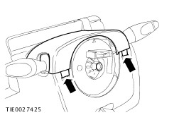
| Removal Details Item 1 : Steering column upper shroud | | -
NOTE:Turn the steering wheel to access the steering column upper shroud retaining clips. Detach the steering column upper shroud from the steering column lower shroud (steering wheel removed for clarity). - Using a thin bladed screwdriver, release the steering column upper shroud retaining clips.
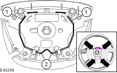
| Item 2 : Driver air bag module | | -
NOTE:Turn the steering wheel to access the driver air bag module retaining clips. Using a thin bladed screwdriver, detach the driver air bag module from the steering wheel (driver air bag module removed for clarity). - Release the driver air bag module upper retaining clips.
- Release the driver air bag module lower retaining clips.
| | | -
WARNING:The driver air bag module must only be inverted long enough to disconnect the electrical connectors. Handle with extreme care making sure that, if for any reason this procedure is interrupted, the driver air bag module is turned the correct way up, with the trim cover side uppermost. Failure to follow these instructions may result in personal injury. NOTE:Note the position of the driver air bag module wiring harness to aid installation. Remove the driver air bag module. - Disconnect the driver air bag module electrical connector.
- Disconnect the horn switch electrical connector.
- Disconnect the driver air bag module ground cable.
- Detach the driver air bag module wiring harness from the driver air bag module.
| Installation Details Item 2 : Driver air bag module | | -
CAUTION:Make sure the driver air bag module wiring harness is correctly routed and is secure under the locating clip. An incorrectly routed driver air bag module wiring harness may become damaged when the steering wheel is rotated. Secure the driver air bag module wiring harness to the driver air bag module. | |