
Contour V6-153 2.5L DOHC (1996)
Electronic Brake Control Module: Diagrams
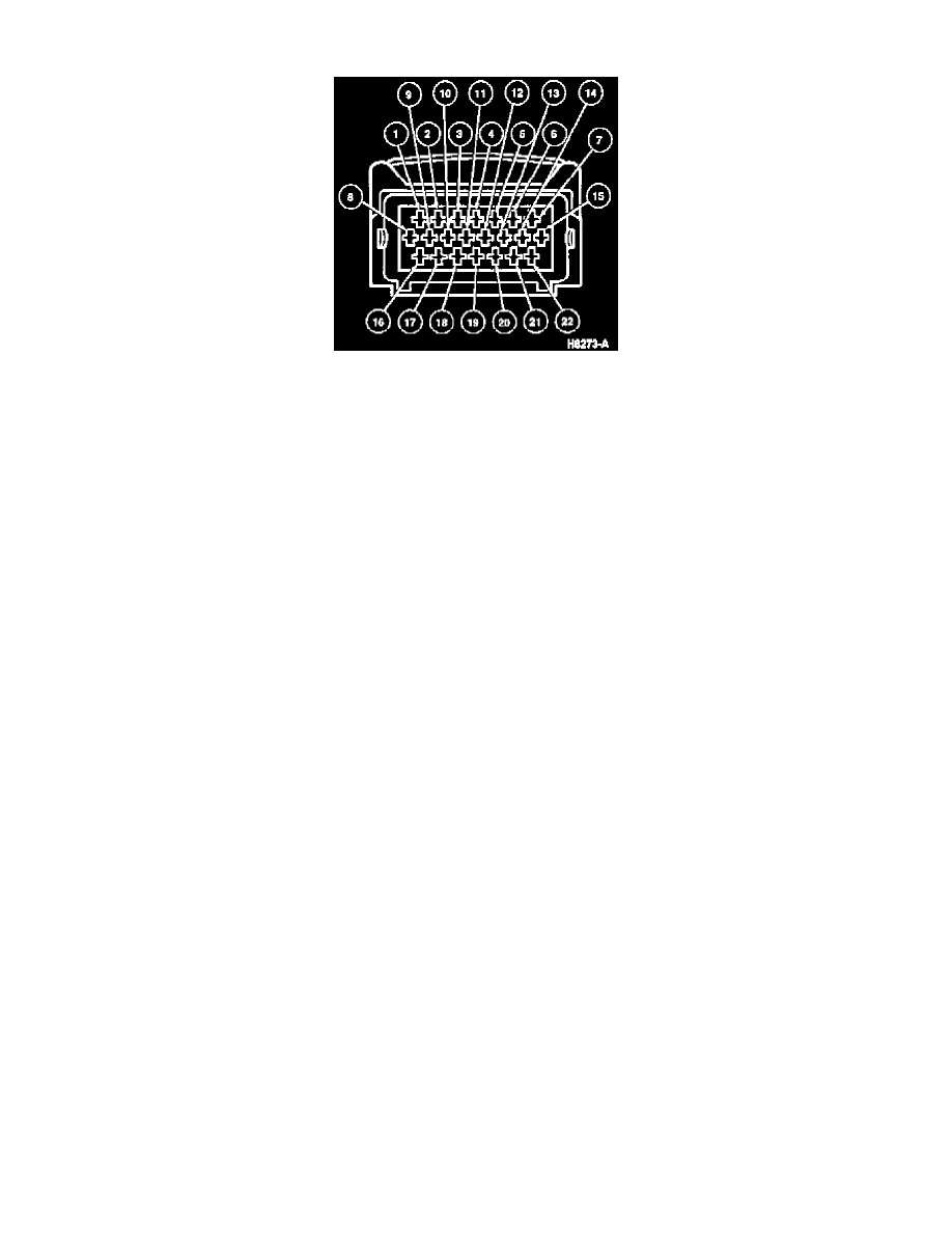
Connector
ABS WITHOUT TRACTION CONTROL
Pin Number
Circuit
Circuit Function
1
8 (W/R)
RH Front Brake Anti-Lock Sensor Signal
2
8 (W/GN)
RH Rear Brake Anti-Lock Sensor Signal
3
8 (W)
LH Front Brake Anti-Lock Sensor Signal
4
Not Used
5
91 (BK/Y)
Ground
6
Not Used
7
Not Used
8
8 (W/BL)
LH Rear Brake Anti-Lock Sensor Signal
9
9 (BR/R)
RH Front Brake Anti-Lock Sensor Return
10
9 (BR)
LH Front Brake Anti-Lock Sensor Return
11
Not Used
12
Not Used
13
Not Used
14
Not Used
15
8 (W/P)
Serial Data Link
16
9 (BR/BL)
LH Rear Brake Anti-Lock Sensor Return
17
9 (BR/GN)
RH Rear Brake Anti-Lock Sensor Return
18
Not Used
19
Not Used
20
Not Used
21
74 (BL)
Power Supply (Ignition)
22
31S (BK/BL)
Anti-Lock Brake Warning Indicator
ABS WITH TRACTION CONTROL
Pin Number
Circuit
Circuit Function
1
8 (W/R)
RH Front Brake Anti-Lock Sensor Signal
2
8 (W/GN)
RH Rear Brake Anti-Lock Sensor Signal
3
8 (W)
LH Front Brake Anti-Lock Sensor Signal
4
Not Used
5
91 (BK/Y)
Ground
6
31S (BK/BL)
Traction Control Warning Lamp
7
31S (BK/W)
Traction Control Sequence Output
8
8 (W/BL)
LH Rear Brake Anti-Lock Sensor Signal
9
9 (BR/R)
RH Front Brake Anti-Lock Sensor Return
10
9 (BR)
LH Front Brake Anti-Lock Sensor Return
11
7 (Y/R)
Traction Control Throttle Potentiometer 5
Volt Supply
12
9 (BR/R)
Traction Control Throttle Potentiometer
Ground