
Contour V6-153 2.5L DOHC VIN L SFI (1997)
Valve Cover: Service and Repair
Left Side
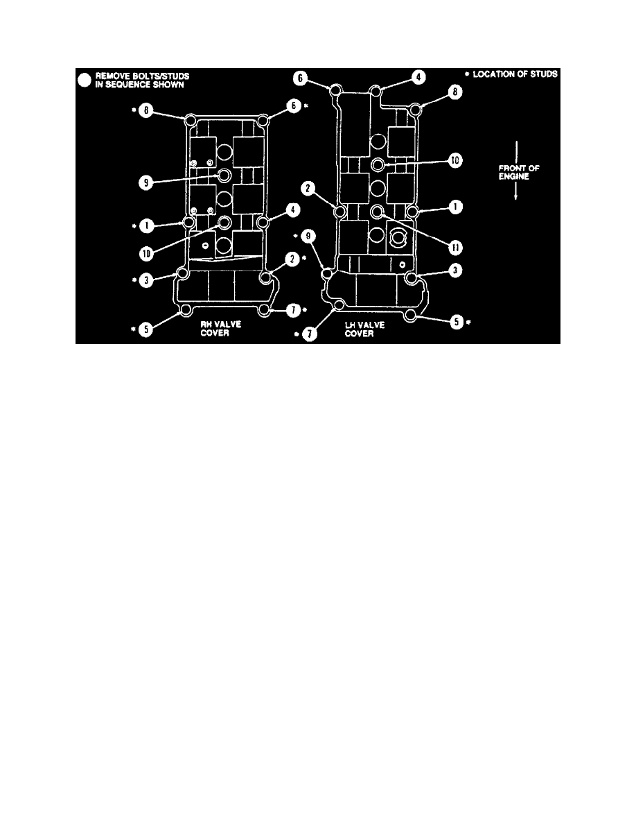
Fig. 13 Valve cover bolt removal sequence
REMOVAL
1. Remove upper intake manifold (9424).
2. Remove ignition wires from ignition coils (12029) and spark plugs (12405). See Powertrain Management.
3. Remove ignition coil. See Powertrain Management.
4. Remove crankcase ventilation tube (6758) from RH valve cover (6582) and remove from vehicle.
5. Remove fuel charging wiring retainer and the retainer nuts and incline connector wiring bracket from the RH valve cover retaining stud bolts.
Position in-line connector wiring bracket and fuel charging wiring (9D930) out of the way.
6. Remove retaining nuts for and engine control sensor wiring (12A581) from RH valve cover retaining stud bolts. Position engine control sensor
wiring out of the way.
7. Loosen valve cover retaining bolts and stud bolts following the removal sequence shown.
8. Carefully remove valve cover from cylinder head (6049). Remove integral valve cover gaskets (6584) from RH valve cover.