
Contour V6-153 2.5L DOHC VIN L SFI (1997)
Resistance/Continuity test
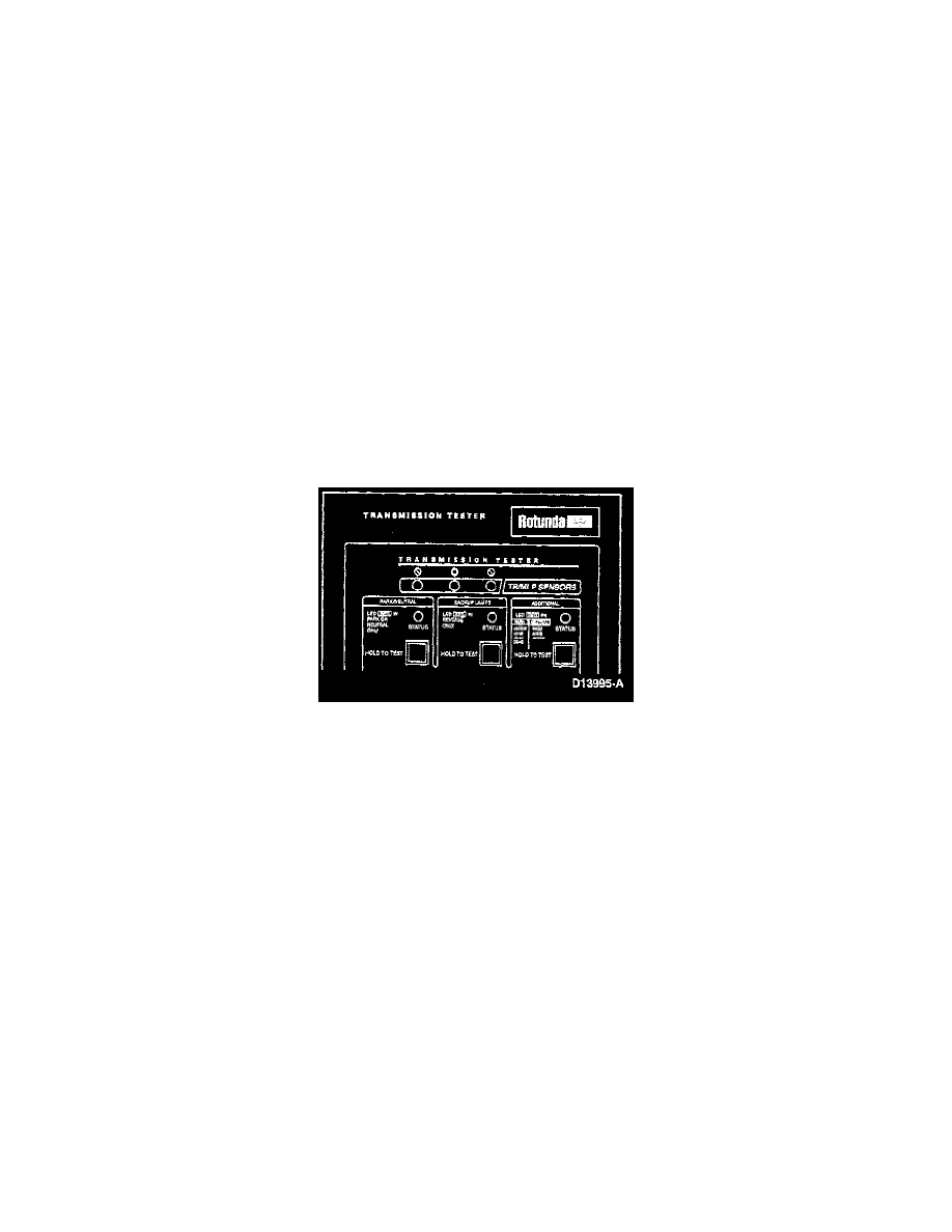
CAUTION: For resistance checks be sure that the LARGE DIAL is set to TR/MLP SENSOR TEST or damage to the ohmmeter could result.
1. Using a digital volt-ohmmeter and the transmission tester, perform Pinpoint Test D or Transaxle Reference Manual based on the DTC displayed.
2. Perform repairs as indicated by the pinpoint test. Always erase all codes, retest and road test vehicle after a repair.
3. Set ohmmeter to 1000 ohms.
4. Connect ohmmeter COM jack to SIG RTN jack.
5. Connect ohmmeter POS lead to TR jack. LED turns OFF when circuit is open.
6. Record resistance in every gear position while moving the shift lever to each position.
7. Refer to the following list:
Shift Lever Position:
Min-Max Resistance (Ohms)
PARK:
3770-4607 Ohms
REVERSE:
1304-1593 Ohms
NEUTRAL:
660-806 Ohms
OVERDRIVE:
361-442 Ohms
SECOND/DRIVE*:
190-232 Ohms
FIRST:
78-95 Ohms
*
Same values for SECOND (electronic transaxle with separate positions for DRIVE and OVERDRIVE).
8. If values are out of range, refer to Pinpoint Test D.
Voltage Tests
NOTE: LED turns OFF when circuit is open.
1. Press and hold each test button while moving the shift lever to each gear position.
2. Monitor each STATUS LED:
NOTE: LED lights red when circuit is closed.
-
The LED in the appropriate gear position you are retesting should light red.
-
If the LED for the applicable gear position fails to light red, or if it lights for a position other than the gear selected verify TR alignment and
retest.
3. If the sensor fails, replace it.
4. After you finish testing, continue to Disconnecting the Tester.