
Courier L4-2299cc Courier (1982)
Positive Crankcase Ventilation: Description and Operation
Description
This system diverts blow-by gases into the intake manifold to be burned by the engine. The system consists of a positive crankcase ventilation
(PCV) valve, an oil separator and the hoses needed to connect these components.
Operation
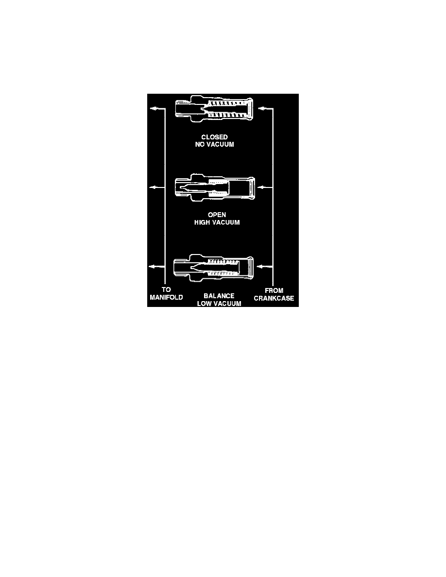
Fig. 1 - PCV Valve Operation
Ventilating air is routed into the rocker cover from the air cleaner, then through the oil separator and to the PCV valve. The PCV valve is operated
by the difference in pressure between the intake manifold and the rocker cover. When there is no difference in pressure or the pressure of the
intake manifold is greater than the rocker cover, the PCV valve is pulled toward the rocker cover by the tension of the valve spring, Fig. 1. If there
is a large difference in pressure, the high vacuum of the intake manifold overcomes the tension of the valve spring and the valve is pulled toward
the intake manifold side by the manifold vacuum, Fig. 1. The air then passes through the restricted passage in the valve. If the difference in
pressure is small, the valve is balanced by the tension of the valve spring and intake manifold vacuum, Fig. 1. This valve position increases the
flow of ventilating air.